


Model DFG-RS3 Digital Force/Torque Indicator
User’s Guide
18
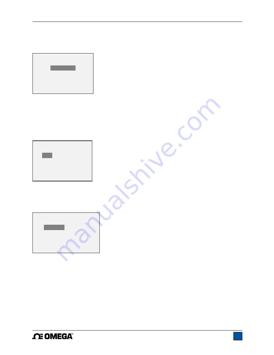
11.3 LCD Contrast
The contrast of the display may be adjusted. Select
LCD Contrast
from the menu. The screen appears
as follows:
Press
ENTER
to modify the contrast. Select a value from 0 to 25, 25 producing the most contrast.
11.4 Tones
Audible tones can be enabled for all key presses and alerts, such as overload, set point value reached,
etc. The Set Point alert can be configured to be either a momentary tone or a continuous tone (until the
load is restored to a value between the set points). To configure the functions for which audible tones will
apply, select
Tones
from the menu. The screen appears as follows:
11.5 Initial Mode
This section is used to configure the initial mode upon powering on the indicator. To access this
parameter, select
Initial Mode
from the menu. The screen will display the available modes, which is
determined by whether a force or torque sensor is connected. An example is as follows:
The default value is Real Time.
11.6 Restore Default Settings
Default factory settings can be restored by selecting
Restore Defaults
from the menu. The settings may
be found in the
Specifications
section. The screen appears as follows:
INITIAL MODE
*
Real Time
Peak Compression
Peak Tension
TONES
Keys
* Alerts
Set Points
* Momentary
Continuous
LCD CONTRAST
Set Contrast
10
Summary of Contents for DFG-RS3
Page 1: ...Model DFG RS3 Digital Force Torque Indicator...
Page 2: ...Model DFG RS3 Digital Force Torque Indicator User s Guide 1...
Page 22: ...Model DFG RS3 Digital Force Torque Indicator User s Guide 21 12 3 Dimensions IN MM...
Page 23: ...Model DFG RS3 Digital Force Torque Indicator User s Guide 22...
Page 24: ...Model DFG RS3 Digital Force Torque Indicator User s Guide 23 M 5250 1017...


