background image

65

GX53

10

10

 Assembly

10-1 Assembly diagram

The numbers in the following diagram represent the order to attach each unit.  
The units shown in the diagram are typical units. For units which are not described below, contact Olympus or refer to 
the latest catalogs.

Before assembling the microscope, remove dust and dirt from the mount of each unit and assemble 
them carefully to prevent from scratches.

The procedures to assemble the units shown by 

 numbers are described on the next page and after.


· Assemble the units using the Allen screwdriver (opposite side: 3 mm 

) and the Allen wrench 

(opposite side: 4 mm or 3 mm 

) provided with the microscope frame. Do not use the Allen 

wrench (Opposite side: 3 mm) for purposes other than attaching the revolving nosepiece.


· For the scale slider GX-SLM, refer to the instruction manuals provided separately.

NOTE

TIP

Stage center plate

Power cord

Connection plate

Filter

Microscope frame

GX53F

Microscope frame

GX53F

Control boxes

Eyepiece

Observation tube

Polarizer

Analyzer

Scale slider

GX-SLM

Filter slider

Stage

Observation tube 

clamping screw

Lamp housing

clamping screws  

(2 positions)

C mount camera 

adapter

Revolving 

nosepiece

Coded 

revolving 

nosepiece

Brightfield 

objective

Adapter

Brightfield/

darkfield 

objective

DIC slider
MIX slider for reflected light observation

LED light source

1

2

4

3

5

7

6

18

17

Digital camera

Light sources other than LED

(See page 78.)

Summary of Contents for GX53

Page 1: ...at you study this manual thoroughly before operating this product and always keep this manual at hand when operating this product Retain this instruction manual in an easily accessible place near the...

Page 2: ...uses and can radiate radio frequency energy and if not installed and used in accordance with the instruction manual may cause harmful interference to radio communications Operation of this product in...

Page 3: ...ng a sample 19 2 Moving the sample 19 3 6 Selecting the objective 20 3 7 Focusing 21 1 Focusing 21 2 Removing the fine focusing knob 21 3 Adjusting the tension of the coarse focusing knob 21 3 8 Adjus...

Page 4: ...r 36 1 Inserting the DIC slider 36 2 Adjusting the prism of the DIC slider 37 4 8 Using the MIX slider for reflected light observation 38 1 Inserting the MIX slider for reflected light observation 38...

Page 5: ...ng cables 74 9 Connecting the AC adapter and power cord 76 10 Attaching the ND filter for darkfield observation 77 11 Attaching the illumination column 78 12 Attaching the halogen bulb for transmitted...

Page 6: ......

Page 7: ...gen bulb Connection of the halogen lamp housing with the power supply GX SLM Scale slider Scale slider GX SLM U LGPS LED and LDP light source Connection of the LED and LDP light source with the liquid...

Page 8: ...cates a potentially hazardous situation which if not avoided may result in minor or moderate injury NOTE Indicates a potentially hazardous situation which if not avoided may result in damage to the eq...

Page 9: ...environment may affect other equipment CAUTION Electric safety Do not look directly at the light from the LED lamp housing for a long time If you feel that the light from LED lamp housing is too brigh...

Page 10: ...mful to your eyes do not light the mercury burner when the lamp housing is not attached to the microscope The lifetime of the illumination device is influenced significantly by operating conditions am...

Page 11: ...ock Do not touch the product with wet hands In particular if you touch the main switch of the power unit or the power cord with wet hands electric shock ignition or failure of the product may be cause...

Page 12: ...Label Instructions in instruction manual Page Left side on rear of microscope frame External power supply for halogen bulb TH4 100 TH4 200 Control box BX3M CBFM Relay unit for coded revolving nosepie...

Page 13: ...ON Carrying the product Remove samples and units attached 1 Make sure that the stage and revolving nosepiece are attached securely If the illumination column is attached make sure that the illuminatio...

Page 14: ...a dust cover during storage 4 Before disposing of this product be sure to check the regulations and rules of your local government and follow them Contact Olympus for any questions 5 If the hour coun...

Page 15: ...epiece Stage center plate Objective Light source for reflected light illumination Microscope frame Polarizer Analyzer Scale slider Eyepiece Scale slider Scale slider Scale slider Analyzer Front port o...

Page 16: ...ame GX53F Observation tube U BI90 U BI90CT U TBI90 U TR30H 2 Intermediate attachment Only one type is usable U CA U ECA U EPA2 GX SPU IX ATU Illuminator Option U DULHA MX HGAD U LLGAD Light source for...

Page 17: ...ightfield Simple polarization Revolving nosepiece U P4RE U P5BDRE U P6RE U 5RE 2 U D6RE U D6RE ESD 2 U D7RE U 5BDRE U D5BDRE U D6BDRE Revolving nosepiece Coded type U 5RES ESD U D5BDRES ESD U D6RES U...

Page 18: ...polarization MIX slider for reflected light observation U MIXR U MIXRCBL Polarizing element GX PO GX POTP GX AN GX AN360 Filter slider GX FSL 25 mm filter 25LBD 25ND6 25ND25 25FR 25IF550 45 mm filter...

Page 19: ...Transmitted light Brightfield Darkfield Brightfield darkfield simultaneously Simple polarization Differential interference contrast Brightfield Simple polarization Controller DP2 SAL Hand switch BX3M...

Page 20: ...7 Filter slider insertion slot P 28 Brightness control knob P 22 Main switch P 16 11 Adjust the aperture diaphragm and the field diaphragm Fully open the aperture diaphragm during darkfield observatio...

Page 21: ...Filter slider insertion slot Y axis knob P 19 Y axis knob P 19 4 X axis knob P 19 4 Coarse focusing tension adjustment ring P 21 Coarse focusing tension adjustment ring P 21 Coarse focusing knob P 21...

Page 22: ...ce U LGPS 1 1 When using the mercury burner the arc image becomes stable 5 to 10 minutes after turning it ON The discharge type mercury burner may not be turned ON in one operation due to its nature I...

Page 23: ...t simple polarization observation DF Reflected light darkfield observation Slide the BF DF selection lever a to select the observation method Slide the lever so that it comes to the click position If...

Page 24: ...h Frame Camera light path Knob on frame a Knob on GX SPU b 100 0 0 50 50 0 20 0 80 10 10 80 Selecting the light path when using the trinocular tube U TR30H 2 The trinocular tube U TR30H 2 can be attac...

Page 25: ...kg can be placed on the stage In this case be sure to install the microscope on a sturdy desk In the environment susceptible to external vibration it is recommended to use the portable anti vibration...

Page 26: ...objective see 6 2 Replacing the objective on page 47 When the coded revolving nosepiece and the hand switch are combined The lighting of the OB indicator a of the hand switch BX3M HS changes according...

Page 27: ...wdriver to remove the fine focusing knob b NOTE 1 The tension of the coarse focusing knob can be changed if necessary Be sure to use the course focusing tension adjustment ring a to adjust the tension...

Page 28: ...n bulb TH4 100 TH4 200 refer to the instruction manual provided with the unit Engage the ND filter in the light path and adjust the transmittance of the illumination light For details see 3 12 Using t...

Page 29: ...the sample into focus Change to the 40X objective or higher again and rotate the coarse focusing knob and fine focusing knob to bring the sample into focus Change to the 10X objective and while looki...

Page 30: ...micrometer rotate the diopter adjustment ring a to adjust so that the scales or lines A in the picture on the left of the eyepiece micrometer in the field of view are clearly visible When you rotate t...

Page 31: ...s 3 Using the eye shades You can adjust the observation tube to the easy to see height and angle so that you can observe with a comfortable posture Hold the binocular section with both hands and move...

Page 32: ...river into both AS centering screws b 2 positions and rotate them to adjust it to come to the center of the field of view Attaching the AS extension lever c provided with microscope frame allows you t...

Page 33: ...ch to adjust so that the field diaphragm image comes to the center of the field Picture B While pushing in the field diaphragm lever a open the field diaphragm gradually until the field diaphragm imag...

Page 34: ...LBD Converts the illumination light of the halogen bulb to the daylight color U 25LBA 25LBA Converts the illumination light of LED to the illumination color of the halogen bulb Green filter U 25IF550...

Page 35: ...into the knob 1 2 3 TIP If the observation light is too bright insert the ND filter in the filter slider insertion slots 2 positions a to reduce the light For details see 3 12 Using the filter sliders...

Page 36: ...yzer and the polarizer Set the DIC slider Adjust the interpupillary distance Adjust the diopter Stage plate P 19 X axis Y axis knobs P 19 Revolving nosepiece P 20 Main switch P 16 Adjust the aperture...

Page 37: ...ght path and bring the sample into focus Observation Select the brightfield BF observation Set the main switch to ON Stage plate P 19 X axis Y axis knobs P 19 Revolving nosepiece P 20 Main switch P 16...

Page 38: ...the light path Select the brightfield BF observation Set the MIX slider for reflected light observation MIX slider for reflected light observation P 38 Brightness control knob P 22 Aperture diaphragm...

Page 39: ...objective in the light path Bring the sample into focus Field diaphragm lever P 42 Aperture diaphragm ring P 42 Adjust the field diaphragm Adjust the aperture diaphragm Adjust the brightness Adjust t...

Page 40: ...plate P 19 X axis Y axis knobs P 19 Revolving nosepiece P 20 Main switch P 41 BF DF selection lever P 17 Brightness control knob P 22 Eyepiece camera light path selection knob P 18 Interpupillary dis...

Page 41: ...to the front side Polarizer insertion position Light path First level pulled out Empty hole Second level pressed in Polarizer Rotate the analyzer rotation dial e to adjust the analyzer Observation wi...

Page 42: ...ion lever d Applicable objectives Pressed in UIS2 MPLFLN MPLFLN BD series MPLAPON series UIS UMPlanFI UMPlanFI BD series MPlanApo20X 100X MPlanApo100XBD Pulled out UIS2 LMPLFLN LMPLFLN BD series UIS L...

Page 43: ...r with the highest sensitivity If you select the magenta sensitive color for the background color even a small phase difference can be viewed as a variation of the color If you want to select the mage...

Page 44: ...IN Tighten the mounting knob a to secure the slider Connect the connector d to the MIX slider for reflected light observation Set the main switch e of the control box BX3M CBFM to ON The buzzer sound...

Page 45: ...brightness of the illumination Button Operation Function Short press Darken by every predetermined quantity Long press Darken continuously Short press Brighten by every predetermined quantity Long pr...

Page 46: ...omatically you cannot operate the dial c and the ON OFF button d 2 NOTE c a Press the MODE button a of the hand switch BX3M HS to select the illumination pattern The indicator b turns ON according to...

Page 47: ...ever e to open the field diaphragm gradually until the field diaphragm image is inscribed in the field of view Picture C If the center of the field diaphragm image is deviated try centering again Open...

Page 48: ...propriate to set the sample used with the microscope between 70 and 80 of the numerical aperture of the objective but you can narrow down the numerical aperture furthermore as needed Using the field d...

Page 49: ...space Even if the illumination column is tilted the sample surface is illuminated which is convenient for checking samples roughly or positioning the samples when placing them When tilting the illumi...

Page 50: ...nd eyepieces Otherwise the focusing of the image through eyepieces will not match with that of the image acquired by the camera For procedures to adjust the parfocality refer to the instruction manual...

Page 51: ...to remove it Depending on the case the reticle holder may be tightened too firmly and it cannot be rotated In this case if you grab the reticle holder too firmly it will be deformed and cannot be rota...

Page 52: ...nnot be used with this tube When using the eyepiece equipped with the micrometer insert the eyepiece into the right eyepiece sleeve In this case attach the eyepiece so that the eyepiece positioning pi...

Page 53: ...tive from the revolving nosepiece Screw the objective to be attached into the screw hole of the revolving nosepiece by rotating it in the arrow direction and secure it firmly Using the brightfield obj...

Page 54: ...clamping screws a 2 positions on the rear of the microscope frame using the Allen screwdriver Be careful if the clamping screw is loosened too much it may come off Remove the lamp housing For details...

Page 55: ...Loosen the clamping screws a 2 positions on the rear of the microscope frame using the Allen screwdriver Insert the halogen lamp housing in the light source mount hole until it touches the end Attach...

Page 56: ...er to the instruction manual provided with the unit 1 2 3 NOTE 4 2 Replacing the mercury burner Loosen the clamping screw a on the top of the lamp housing using the Allen screwdriver 1 Hold the upper...

Page 57: ...cury burner e to the fixed mount on the upper side then attach the negative pole to the mount on the lower side Be careful not to touch the burner directly with your hand and avoid leaving fingerprint...

Page 58: ...main switch on page 16 Engage the light shielding plate of the filter slider a to block the illumination light Use the observation light path selection knob to set the BF light path During centering...

Page 59: ...the center of the right or left half of the field of view Picture B Fit the Allen screwdriver into the mirror focusing screw h on the rear of the lamp housing and rotate the screw to bring the mirror...

Page 60: ...up Insert the precision screwdriver in the notch a of the cover diagonally and raise and slide the cover with the precision screwdriver to open the cover Insert the arbitrary filter in the filter moun...

Page 61: ...ise to remove the filter holding ring b Insert the filters with display surfaces e of the slider facing up Screw in the holding ring b to clamp firmly When using two filter sliders Insert the filters...

Page 62: ...iddle position Move the knob to the stop position according to the purpose 18 The revolving nosepiece is not set to the click position properly Set it to the click position properly 20 The lamp housin...

Page 63: ...6 j The one sided blur appears in the observed image The lamp housing is not attached properly Push it to the stop position completely and secure it 48 50 The objective is not properly engaged in the...

Page 64: ...is damaged Contact Olympus 4 Observation tube a The fields of view of two eyes do not coincide The interpupillary distance is not correct Adjust it correctly 23 The diopter difference is not correcte...

Page 65: ...Set the main switch to OFF and connect the hand switch BX3M HS 38 76 The hand switch BX3M HS is damaged Contact Olympus The cable of the revolving nosepiece or GX IFRES is not connected Set the main s...

Page 66: ...ame Halogen lamp housing U LH100L 3 Applicable bulb 12V100WHAL L long life type made by PHILIPS Co 7724I Lifetime Approx 2 000 hours Used in accordance with rating 12V100WHAL high light intensity type...

Page 67: ...and DIC observations Slider For differential interference contrast U DICR Standard type U DICRHC High resolution type U DICRHC High contrast type For MIX U MIXR Equipped with LED ring illumination li...

Page 68: ...00X MPLAPON M Plan Apochromat 50X 100X LCPLFLN LCD Long working distance M Plan Achromat 20X 50X 100X 1 For reflected light brightfield observation 2 Not available for reflected light DIC observation...

Page 69: ...M Plan Semi Apochromat BD OFN26 5 MPlanFLN BD 5X 0 15 12 0 50X 4 4 50X 5 3 10X 0 30 6 5 100X 2 2 100X 2 65 20X 0 45 3 0 0 200X 1 1 200X 1 33 50X 0 80 1 0 0 500X 0 44 500X 0 53 100X 0 90 1 0 0 1000X 0...

Page 70: ...ective Ex M PL Plan FL N 100 BD None For brightfield BD For brightfield darkfield BDP For brightfield darkfield polarization IR For IR Number Objective magnification None UIS objective N UIS2 objectiv...

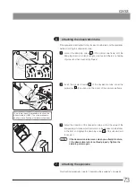
Page 71: ...mm or 3 mm provided with the microscope frame Do not use the Allen wrench Opposite side 3 mm for purposes other than attaching the revolving nosepiece For the scale slider GX SLM refer to the instruc...

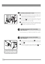
Page 72: ...rder to attach the liquid light guide or the mercury lamp housing the optional adapter MX HGAD is required Loosen the clamping screws a 2 positions of the microscope frame using the Allen screwdriver...

Page 73: ...double lamp housing adapter U DULHA so that the a part shown in the following picture comes to the left side horizontally when facing to the back side of the microscope frame NOTE a Adapter MX HGAD L...

Page 74: ...roscope frame Be careful if the clamping screw is loosened too much it may come off When attaching or detaching the coded revolving nosepiece be sure to remove the cable from the connector in advance...

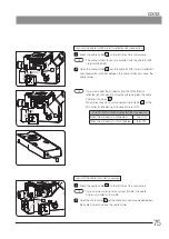
Page 75: ...hesive power becomes weak and the product may drop Decide the position carefully before attaching it to prevent from attaching again Hold GX IFRES b and connect the connector of the coded revolving no...

Page 76: ...holder a Attach the U CBS holder to the other U CBS mounting hanger e and attach the U CBS holder f to the back of the microscope Be careful not to attach the U CBS over the label on the back of the m...

Page 77: ...n page 74 Set the DIP switch No 4 on the side of the control box BX3M CBFM to ON Illumination pattern 2 1 2 4 Attaching the MIX slider DIC slider for reflected light observation Factory default settin...

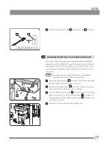
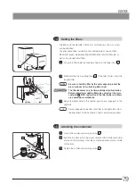
Page 78: ...SFR Fit the shaft f of the flexible handle into the U shaped groove of the handle holder e Secure the handle holder clamping screw g to the stage lightly using the Allen screwdriver Align the stage c...

Page 79: ...f the microscope frame Adjust the direction of the observation tube so that the value of the interpupillary distance adjustment scale on the observation tube faces to the front and tighten the clampin...

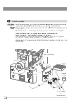
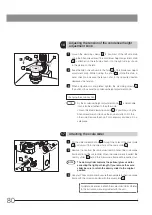
Page 80: ...bent or twisted Never subject them to excessive force Be sure to connect only cables specified by Olympus to the connectors Connect the connectors in the correct orientation paying attention to the sh...

Page 81: ...tion store the cable between the cable holder as shown as b When the connector is disconnected the indicator c of the MIX slider for reflected light observation turns OFF Indicator of MIX slider for r...

Page 82: ...ct the power cord Connect the power cord plug to the grounded triplex outlet If the outlet is not grounded the electric safety performance intended by Olympus cannot be assured If the power cords cont...

Page 83: ...scope frame Loosen the clamping screws a 2 positions of the mirror cover using the Allen screwdriver to remove the mirror cover Set the BF DF selection lever b to DF side The BF mirror comes closer to...

Page 84: ...t screws b 4 positions using the provided Allen wrench 1 2 3 For attaching procedures see Replacing the halogen bulb on page 48 Loosen the lamp housing clamping screws a 2 positions of the illuminatio...

Page 85: ...g dirt or dust The filter becomes very hot immediately after illumination Before replacing or adding filters be sure to set the main switch to OFF and wait until the filter holder and filters are cool...

Page 86: ...knob and attach it to the other side Remove the knob if not necessary and keep it in a safe place 1 2 3 TIP a c b 17 Attaching the scale slider Put the slider selection knob a through the holes of the...

Page 87: ...e Set the main switches of the microscope and TV camera to ON and bring the sample into focus precisely by observing it through the eyepieces Rotate the TV camera d so that the image on the TV monitor...

Page 88: ...me exceeds 20 000 hours of use 2 Light flickers when you move a lamp cable or illumination devices only when using the halogen bulb 3 Dirt or substances are attached around the main switch 4 The light...

Page 89: ...ed by one of the agencies mentioned in Table 1 please use replacements approved by any other equivalent and authorized agencies in your country Country Agency Certification mark Country Agency Certifi...

Page 90: ...Cables BASEC BASEC HAR 10 10 30 N V KEMA KEMA KEUR HAR 10 30 30 SEMKO AB Svenska Elektriska Materielkontrollanstalter SEMKO HAR 10 10 50 sterreichischer Verband f r Elektrotechnik VE VE HAR 30 10 50...

Page 91: ......

Page 92: ...Distributed by Manufactured by Shinjuku Monolith 2 3 1 Nishi Shinjuku Shinjuku ku Tokyo 163 0914 Japan www olympus global com AX9460 02 Issued in April 2021...

Reviews: