background image

DSX1000

"Attachment/detachment of the stage" (34 page)

NOTE

As the transport locks will be used for transporting the system next time, keep them in a safe place.

4.2 General

NOTE

This product is a precision instrument. Handle it with care and avoid subjecting it to a sudden or severe

impact.

Do not use the product in areas where it may be subjected to direct sunlight, high temperature and/or

humidity, dust or vibrations.

(For conditions of operating environment, see

"Specifications" (14 page)

.)

For units attachable to this product, see

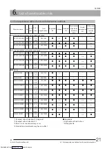
"List of combinable units" (21 page)

The use of this product in

combination with other separately available items not only creates the risk of abnormal operation, but it also

may damage the product.

The included power cords are for exclusive use of this product. Do not use it in combination with other

products.

If you need to package this product, such as to ship to the distant location, you must use the dedicated

package box. In this case, be sure to contact Olympus for assistance.

If you observe a sample that contains a toxic substance, comply with laws and regulations in the environment

where you use this product and the rules for handling the toxic substance. After observation, clean any part

that touched the sample, e.g. stage, objectives, etc.

The sliding sound of the tilting frame or the operating sound of the stage may become louder or the vibration

of the stage may increase depending on the operating environments or use status, but this is not malfunction.

You are not allowed to add any objective that is not described in

"List of combinable units" (21 page)

to this

system.

Do not repair the system by yourself. If you repair or move this system yourself, Olympus shall not be liable for

any consequence even if the product malfunctions or is damaged. Also, even during the guarantee period, the

free-repair may not be applied in some cases.

Attaching or detaching the parts of this system cannot ensure the performance of this system.

Before disposing of this product, be sure to follow the regulations and rules of your local government.

Glasses and solders used in this system are lead-free.

4.3 Confirmation of accessories

The accessory list is provided with the zoom head, stage and microscope frame respectively. After taking all items out from

the package, make sure that all items are provided.

If any item is missing or damaged, contact Olympus.

13

4.2 General

4. Handling Precautions

Downloaded from 

ManualsNet.com

 search engine

Summary of Contents for DSX1000

Page 1: ...f fully with the use of this product we recommend that you study this manual thoroughly before operating this product and always keep this manual at hand when operating this product Retain this instru...

Page 2: ...sible for compliance could void the user s authority to operate the product FCC Supplier s Declaration of Conformity Hereby declares that the product Product name Optical Microscope Optical Microscope...

Page 3: ...3 5 Prevention of eye injury 7 3 6 Prevention of injury 8 3 7 Safety symbols 9 4 Handling Precautions 11 4 1 Detaching the transport locks 12 4 2 General 13 4 3 Confirmation of accessories 13 5 Speci...

Page 4: ...ent of the lens attachment 41 8 7 Attachment detachment of the polarized illumination adapter 42 8 8 Attachment detachment of the diffused illumination adapter 43 8 9 Attachment detachment of the LED...

Page 5: ...y precautions DSX1000 Instruction Manual Hardware this manual Safety precautions specifications and assembly method DSX1000 Instruction Manual Operation Observation methods image correction measuremen...

Page 6: ...a potentially hazardous situation which if not avoided could result in death serious injury or damage to the sample CAUTION Indicates a potentially hazardous situation which if not avoided may result...

Page 7: ...ropriate samples include semiconductors electronic components molded parts or mechanical parts Industrial applications include observation inspection or measurements Do not use this product for any pu...

Page 8: ...prox 6 kg Manual stage adapter DSX10 MSTAD Approx 4 kg Disconnect the cables before carrying the microscope Be careful not to pinch your fingers or other body parts when placing the zoom head on the d...

Page 9: ...ox In this case be sure to contact Olympus for assistance If you transport and install this system overseas by yourself without prior notice to Olympus the services in the destination country will not...

Page 10: ...the product with wet hands In particular if you touch the main switch of the power unit or the power cord with wet hands electric shock ignition or failure of the product may be caused Do not bend pul...

Page 11: ...r cords Electrical short circuit or fire could be caused Do not connect the power cords to the power supply voltage other than that specified in the instruction manual Otherwise it could cause a fire...

Page 12: ...f the microscope Your fingers could be pinched While using the polarized illumination adapter do not touch the polarized illumination adapter except the adjustment lever The temperature around the pol...

Page 13: ...g it to ON or OFF side Indicates that the seesaw type main switch is OFF Safety labels are placed on the portions which particularly require special cautions when using or operating this product Be su...

Page 14: ...l Prevention of electric shock 6 page Electric safety 6 page Prevention of electric shock 6 page Electric safety 6 page Prevention of electric shock 6 page Electric safety 6 page Attaching the PCIe in...

Page 15: ...he operating system supports Japanese and English only The controller is dedicated to this system If you add hardware which is not specified by Olympus to the controller the system operation is not gu...

Page 16: ...plication once And then turn off and on the power of the microscope frame or that of the control box again and restart the application If the status is not improved restart the controller If you termi...

Page 17: ...his product and the rules for handling the toxic substance After observation clean any part that touched the sample e g stage objectives etc The sliding sound of the tilting frame or the operating sou...

Page 18: ...0 01 m Stage Manual stage U SIC4R2 Movable range 100 mm H x 105 mm W Equipped with function to lock in Y axis direction Rotatable motorized XY stage DSX10 RMTS Movable range 100 mm H x 100 mm W 1 Rot...

Page 19: ...g working distance objective lens 3X DSX10 XLOB3X NA0 09 WD30 0 Tiltable angle 56 9 Long working distance objective lens 10X DSX10 XLOB10X NA0 30 WD30 0 Tiltable angle 57 4 Long working distance objec...

Page 20: ...ent the monitor magnification will be different Controller Controller PC Windows 10 Pro English or Japanese 64bitOS Control box Control box DSX10 CB Control of zoom head DSX10 UZH DSX10 SZH Communicat...

Page 21: ...l assistance tool of OLS51 S ETA cannot be used 5 2 Dimension and weight Unit Name Dimension mm Weight kg Universal zoom head DSX10 UZH 180 W x 430 D x 365 H 11 0 Standard zoom head DSX10 SZH 180 W x...

Page 22: ...0 8 Control box DSX10 CB 100 W x 302 D x 149 H Excluding screws and other protrusions 2 6 LED transmitted light illuminator DSX10 ILT 112 W x 112 D x 19 H 0 3 Objective lens case DSX10 LC 434 W x 291...

Page 23: ...voltage Rated voltage 10 Pollution degree 2 in accordance with IEC60664 Installation category excess voltage category II in accordance with IEC60664 Installation location Flat surface The product does...

Page 24: ...vironmental standards RoHS Europe only In compliance with the rules of environment related substance management for Olympus group product 20 5 Specifications 5 8 Measures for safety and environmental...

Page 25: ...5 0 07 0 69 560X 5600X 4 UIS2 Series MPLFLN1 25X 0 04 3 50 2 19 17 1 23X 175X 3 MPLFLN2 5X 0 08 10 7 1 1 10 2 38X 350X 3 MPLFLN5XBDP 0 15 12 0 0 55 5 48 70X 700X MPLFLN10XBDP 0 25 6 5 0 27 2 74 140X 1...

Page 26: ...ive MPLAPON50X 2 MPLFLN1 25X 2 MPLFLN2 5X 2 MPLFLN5XBDP MPLFLN10XBDP MPLFLN20XBDP MPLFLN50XBDP LMPLFLN10XBD LMPLFLN20XBD LMPLFLN50XBD 2 The adapter BD M AD is necessary Lens attachment for UIS DSX10 L...

Page 27: ...achment and the zoom head are connected Be careful not to wipe off the lubricant too much Portions other than lenses Wipe the portions other than lenses with a dry soft cloth If dirt dust cannot be re...

Page 28: ...g DSX1000 Store this product in the temperature range of 0 to 40 Store this product in the environment without drastic temperature fluctuation 10 C h or more When the tilting frame DSX10 TF is combine...

Page 29: ...Connecting with the control box Optional 47 page If you attach the zoom head to your system refer to Attaching the zoom head DSX10 UZH DSX10 SZH provided with the control box DSX10 CB 8 2 Detachment...

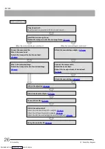
Page 30: ...ach the motorized stage Detach the transport locks of motorized stage 34 page Connect the camera cable Attach the zoom head Detach the transport locks of zoom head 31 page Attach the manual stage 38 p...

Page 31: ...cable 44 page Detach the lens attachment 41 page Detach the objective 40 page When the motorized stage is combined When the manual stage is combined Detach the motorized stage Attach the transport lo...

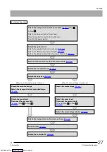
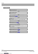
Page 32: ...to BIOS OS settings of PC provided with DSX10 BSW Install the device driver 48 page Install the basic software DSX10 BSW Refer to Installation and Uninstallation of DSX10 BSW provided with DSX10 BSW...

Page 33: ...es the PCIe IF board refer to Attaching the PCIe interface board 53 page Uninstall the software Disconnect the USB license key 49 page Uninstall the basic software DSX10 BSW Refer to Installation and...

Page 34: ...ck clamping screw 1 position using the Allen screwdriver provided with the zoom head Detach the transport locks Attaching the transport locks Rotate the focusing knob to lower the stage mount to the l...

Page 35: ...urely with both hands l Be careful not to pinch your fingers or hands l If you carry the zoom head do not hold the camera head Attaching the zoom head Place the zoom head on the desk with its left sid...

Page 36: ...duct could be damaged Be sure to detach it l As the transport screw will be used for transporting the system next time keep it in a safe place Detaching the zoom head Move the zoom head until the Z po...

Page 37: ...e back of the control box The procedures to attach the transport locks and detach the zoom head form the microscope frame are reverse to the procedures of Attaching the zoom head Place the detached zo...

Page 38: ...using knob to lower the stage mount sufficiently Loosen the stage clamping screw 1 position of the stage mount Loosen the clamping screws 3 positions of the stage position adjustment screws of the sta...

Page 39: ...ecure the washers between the stage and the transport lock plate as shown in the picture above Make sure that the tip of the stage plate clamping screw of the stage is not protruded and place the stag...

Page 40: ...ps 4 pcs provided with the stage to the holes at four corners of the stage NOTE If you attach the rotatable motorized XY stage DSX10 RMTS the centering and the XY alignment are necessary For details s...

Page 41: ...e manual stage adapter DSX10 MSTAD and detach the base of the stage While pushing the manual stage adapter in the arrow direction tighten the clamping screws outside 3 positions provided with the manu...

Page 42: ...ge mount and tighten the provided clamping screws to secure the manual stage adapter TIP To detach the manual stage adapter perform the procedure described above in reverse order 8 4 3 Attaching detac...

Page 43: ...MSSP4 Detach the folding prevention pins 2 pcs placed at the bottom of the stage plate U MSSP4 Place the stage plate on the stage and tighten the clamping screws 2 pcs TIP To detach the stage plate p...

Page 44: ...mouth visit the doctor and follow the instruction Screw the objective into the lens attachment XLOB Series UIS2 Series NOTE l There are restrictions for the combination of the objective and the lens a...

Page 45: ...the lens attachment to the objective exchange position see 2 1 2 Replacing the lens attachment in Operation manual Attaching the lens attachment Insert the lens attachment along the zoom head mount a...

Page 46: ...king distance objective lens with the protrusion of the polarized illumination adapter DSX10 POAD Attach the polarized illumination adapter by rotating it in right direction until the click sound is h...

Page 47: ...ive lens with the protrusion of the diffused illumination adapter DSX10 DIAD3X or DSX10 DIAD1X10X Attach the diffused illumination adapter by rotating it in right direction until the click sound is he...

Page 48: ...g the power cords from the outlet l As this system includes motorized portions do not connect the power cord until you complete connecting all other cables l Cables and cords are vulnerable to bend or...

Page 49: ...ransmitted light illuminator you need to register it in the application For details see 1 8 2 Registering the optional unit in Operation manual Connecting with the zoom head DSX10 UZH or DSX10 SZH Uni...

Page 50: ...ble binder position of the tilting frame DSX10 TF using the cable binder provided with the tilting frame DSX10 TF The illustration shows the case of the tilting frame DSX10 TF but the same cable binde...

Page 51: ...than the DSX1000 series microscope frame DSX10 TF or DSX10 UF connect the control box DSX10 CB This procedure is necessary only for the user who purchased the zoom head alone Connection to Zoom head...

Page 52: ...ccount is registered as Administrator NOTE l Before installing the device driver close all open applications l Install the device driver before installing the Basic software DSX10 BSW l Attach the PCI...

Page 53: ...Program Files OLYMPUS DSX BSW Common Help Win10_SystemBackUp_Restoration_Procedures_E pdf l https www olympus ims com resources manuals Search for System backup and restoration of Windows10 in the ke...

Page 54: ...oscope frame in the package box and then cover it with the pad in the appropriate direction Cover the microscope frame with the pad in the direction shown in the picture below 50 8 Assembly 8 13 Packa...

Page 55: ...ne of the agencies listed in Table 1 or comprised of cordage marked with an agency marking per Table 1 or marked per Table 2 The fittings are to be marked with at least one of the agencies listed in T...

Page 56: ...MA KEUR HAR 10 30 30 SEMKO AB Svenska Elektriska Materielkontrollanstalter SEMKO HAR 10 10 50 sterreichischer Verband f r Elektrotechnik VE VE HAR 30 10 50 Danmarks Elektriske Materialkontroll DEMKO D...

Page 57: ...he controller PC equipped with PCIe interface board using the cart without packaging be careful not to allow it to collide with nearby walls or desks etc and get over the steps slowly and gently l Do...

Page 58: ...t touch the parts on the board surface or push it with excessive force to prevent the damage Be careful not to let power cords be caught by the parts inside the controller PC l When inserting the PCIe...

Page 59: ...oard Otherwise it may deteriorate product performance l Graphic board l PCIe interface board of DP80 DP73 or DP72 l Board with power consumption of 3 W or more Connect the connector to the SATA power...

Page 60: ...AX9336 06 Issued in September 2021 Downloaded from ManualsNet com search engine...
Reviews: