DSX1000
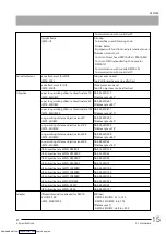
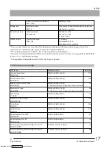
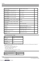
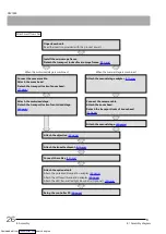
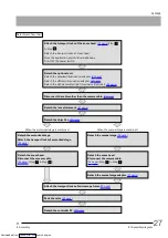
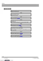
8.1 Assembly diagram
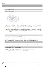
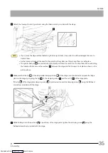
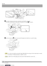
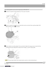
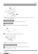
It is recommended to request Olympus to assemble this product to secure its performance.
NOTE
For installation, remove dirt or dust from the attaching portions and be careful not to scratch them.
The above illustration shows the case of the tilting frame DSX10-TF, but the same applies to the upright frame DSX10-UF.
For the assembly using the control box DSX10-CB, see
"Connecting with the control box (Optional)" (47 page)
.
If you attach the zoom head to your system, refer to "Attaching the zoom head DSX10-UZH / DSX10-SZH" provided with
the control box DSX10-CB
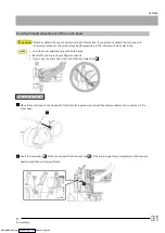
8.2 Detachment of
transport locks of
microscope frame
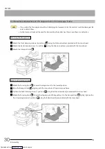
8.3 Attachment of the zoom head
8.6 Attachment of the lens attachment
8.4 Attachment of the stage
8.5 Attachment
of the objective
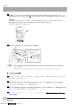
8.7, 8.8 Attachment of the adapter
8.10 Connection of the
cables
8.9 LED transmitted light illuminator
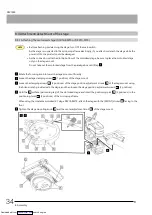
8.10 Control box
8.10 Console
8.
Assembly
25
8.1 Assembly diagram
8. Assembly
Downloaded from


