27
BX61WI
Fig. 38
Fig. 39
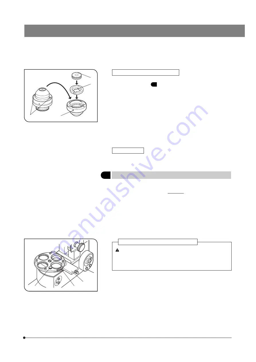
With the WI-DICD Condenser (Fig. 38)
}The WI-DICD should be attached after completing the polarizer position
as described in item
5
.
1. Remove the WI-DICD condenser from the microscope frame.
2. Remove the two clamping screws
1
using the Allen screwdriver provided
with the microscope, then place the top of the condenser upside down.
3. When the DIC prism for use with the objective in use is a small DIC
prism, drop it in by aligning the positioning groove
2
on the adapter
located on the inner side with the pin
3
of the prism.
When the DIC prism for use with the objective is a large DIC prism,
remove the adapter and drop in the DIC prism.
}Retain the adapter for future possible use.
4. Tighten the clamping screws
4
with the knob provided with the condenser.
5. Attach the condenser on the microscope again.
With the U-UCD8
}Attach the DIC prism by referring to the instruction manual provided with
the U-UCD8.
5
Adjusting the Polarizer Position
(Fig. 39)
}This adjustment is possible without removing the DIC prism (for revolving
nosepiece). However, it is not possible if a DIC prism for condenser is
engaged in the light path. Remove or disengage the DIC prism for con-
denser as described below.
· WI-DICD: Remove the DIC prism.
· WI-UCD: Rotate the turret to engage a position without DIC prism.
Be sure to take the following measure to protect your eyes from
the IR rays.
}Insert the IR cut filter (light blue) provided with the microscope into
the filter slider
1
then push it in to engage it.
1. Remove the condenser from the microscope.
2. Remove an objective and engage the position without the objective in
the light path.
3. Engage the polarizer and analyzer in the light path (page 24) and turn the
transmitted light on.
When the U-LH100IR Lamp Housing Is Used
1
2
3
4
1
2
3
# This adjustment is not necessary when the U-UCD8 is used. How-
ever, be sure to insert the WI-TP137 quarter-wave plate in a position
where the U-UCDTP530 one-wave plate for the U-CD8 is otherwise
inserted.


