14
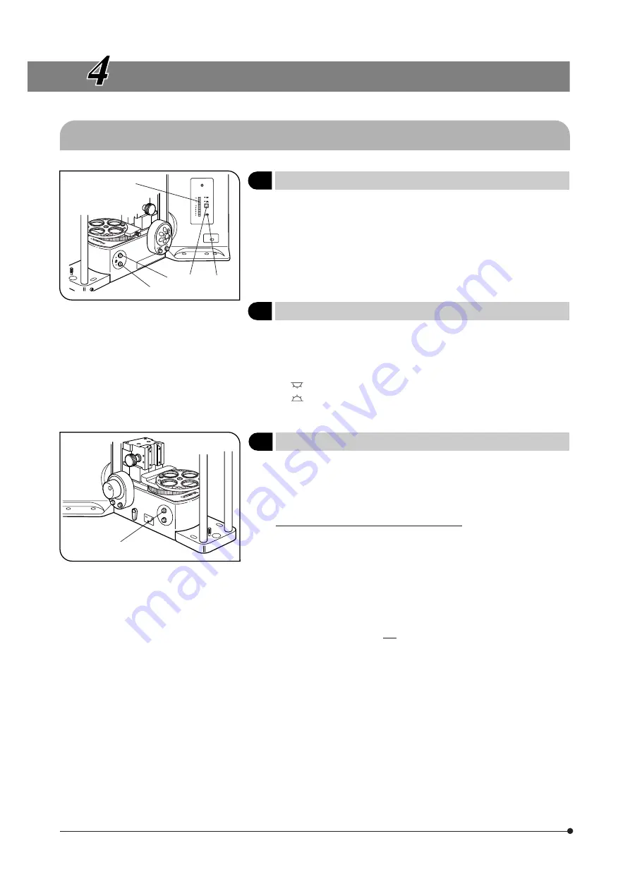
Fig. 3
Fig. 4
USING THE CONTROLS
4-1 Microscope Frame
1
Voltage Indication
(Fig. 3)
1. Press the light intensity control button
1
to increase the voltage and
make illumination brighter.
Pressing the button
2
makes the illumination darker.
2. The numerals to the left of the lamp voltage indicator LEDs
3
indicate
the reference values of the voltages.
# The LEDs may turn off (temporarily) when the motor is driven, but the
illumination intensity even if this occurs.
2
Transmitted/Reflected Light Switch
(Fig. 3)
}The same effect as this switch can also be obtained using the switch on
the U-FH focus adjustment knob unit (see page 15).
The illumination can be switched between the transmitted light and
reflected light by pressing the transmitted/reflected light switch
4
.
: Reflected light illumination
: Transmitted light illumination
The LED indicator of the selected illumination lights.
3
Light Preset Switch
(Fig. 4)
}The Light Preset switch sets the light intensity voltage to a voltage suitable
for color photography* (the factory default is 9 V) regardless of the current
setting of the light intensity control buttons.
* Achieved by engaging the LBD filter.
Setting the Desired Brightness (Figs. 3 & 4)
1. Press the Light Preset switch
5
. The PHOTO indicator LED
6
lights up.
2. Press one of the light intensity control buttons
1
and
2
to set the desired
brightness.
3. Press the Light Preset switch again. The LED turns off, the brightness
returns to the original brightness but the setting made above is stored in
memory.
4. Hereafter, pressing the Light Preset switch sets the brightness to the
intensity value set in step 2 above.
# Be sure to return to the 9 V setting when performing color photogra-
phy.
}When the Light Preset switch
5
is pressed, an announcement tone (short
beep) is generated at the 9 V position of the switch.
}When the external TH-4 power supply unit is used instead of the
microscope’s built-in power supply circuitry, refer to the instruction manual
provided with the TH4.
1
2
3
4
6
5


