8.
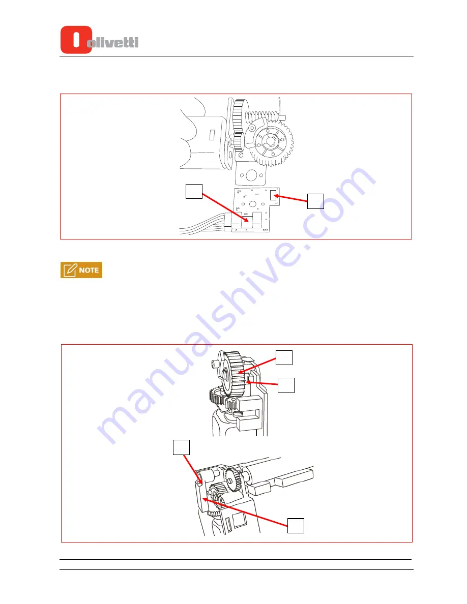
Remove the photosensor unit comprising of:
–
cutter positioning photosensor (1);
–
clam closure photosensor (2).
2
1
Figure 4-13
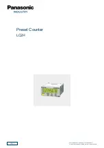
For reassembly carry out the same procedures in reverse order taking care to follow these
instructions:
put the photosensor unit back into position correctly, making sure that the cam (2) covers the cutter
position photosensor (1) as shown in the figure.
When reassembling the control lever (3) of the mobile blade, make sure that it matches up correctly
with the cogwheel pin (4) as shown in the figure.
After the Cash Register has been completely reassembled perform the printer unit photosensors
calibration using the Diagnostic Tool “
DiagNettuna7000I 1.00.04.0.2
” or later version.
1
2
1
3
4
Figure 4-14
4-8
Service Manual
Y117850-4
Summary of Contents for NETTUNA 7000 Open
Page 1: ...Cash Register NETTUNA 7000 Open SERVICE MANUAL Code Y117850 4...
Page 4: ...Page intentionally left blank...
Page 14: ...Figure 1 6 1 8 Service Manual Y117850 4...
Page 24: ...1 18 Service Manual Y117850 4 This page is intentionally left blank...
Page 31: ...2 Press the power key Figure 2 7 Y117850 4 Service Manual 2 7...
Page 32: ...2 8 Service Manual Y117850 4 This page is intentionally left blank...
Page 58: ...3 26 Service Manual Y117850 4 This page is intentionally left blank...


