Field Service Ver. 3.0 Jan. 200
10
. Jam display
87
FS-519/PK-515/OT
-602
T
roubleshooting
10
.3.4
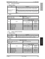
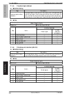
Exit section misfeed
A. Detection timing
B. Action
10
.3.5
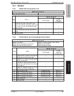
Finisher bundle exit misfeed
A. Detection timing
B. Action
Type
Description
Finisher exit section mis-
feed detection
The transport sensor (PS2) is not turned ON even after the set period of
time has elapsed after the entrance sensor (PS1) is turned ON by the
paper.
The transport sensor (PS2) is not turned OFF even after the set period of
time has elapsed after the entrance sensor (PS1) is turned OFF by the
paper.
Relevant electrical parts
Entrance sensor (PS1)
Transport sensor (PS2)
FS control board (FSCB)
MFP board (MFPB)
Step
Action
WIRING DIAGRAM
Control signal
Location
(Electrical
component)
1
Initial check items
—
—
2
PS1 I/O check, sensor check
FSCB PJ19-11 (ON)
FS-519 C-7
3
PS2 I/O check, sensor check
FSCB PJ19-14 (ON)
FS-519 C-7
4
Change FSCB
—
—
5
Change MFPB
—
—
Type
Description
Finisher bundle exit
misfeed detection
The storage tray detect sensor (PS3) is not turned OFF even after the set
period of time has elapsed after the exit motor (M4) is energized.
Relevant electrical parts
Storage tray detect sensor (PS3)
Exit motor (M4)
FS control board (FSCB)
Step
Action
WIRING DIAGRAM
Control signal
Location
(Electrical
component)
1
Initial check items
—
—
2
PS3 I/O check, sensor check
FSCB PJ14-8 (ON)
FS-519 C-12
3
M4 operation check
FSCB PJ10-5 to 8
FS-519 C-3
4
Change FSCB
—
—
Y10
8442-7
Service Manual


