background image

27 / 47 


Date


30/9/2016


File 


Document code 

921163800_09_007


Page 

 27 from 47


4.4 

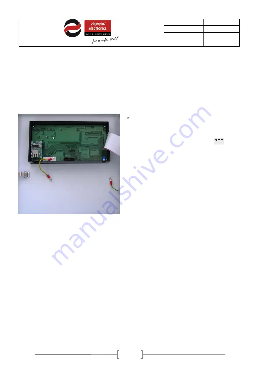
Describing the interior of the panel 

To access the interior of the panel we must open the lock on the front lid.


The BS-1638 panel main consists of two sections:


1. The left section which is the lid and contains the main pcb with the controller, the indication pcbs and 
the lock. 

2. The right section contains the power supply, the zone and input/output pcbs, the battery compartment 
and the cable entry holes. 


220-240V  AC

L

N


Figure 4-21. Panel Interior 

4.5 

Connecting the power supply cables (220-240V AC) 

The panel has cable entry holes for all the cables. You can connect cables with a maximum diameter of 
2.5mm to the terminal blocks. 

The power supply cables of the panel must be with double insulation. The power supply cable must also 
contain a power earth cable that must be connected to the main power earth connection of the building. 

Summary of Contents for BS-1638

Page 1: ...BS 1638 BS 1642 BS 1646 Conventional fire detection panels 8 12 and 16 Zones Installation Programming Use WARNING READ THE WHOLE MANUAL BEFORE EVERY INSTALLATION ...

Page 2: ...st Led 13 2 7 Information 13 2 7 1 Zone Information 15 3 User Menu17 3 1 Enable Disable menu 19 3 2 Delay menu 19 3 3 Adjusting the time and date 19 3 4 Changing the user code 20 3 5 Use a P C to access the user menu 21 3 5 1 Using a personal computer 21 3 5 2 Panel information 22 3 5 3 Zone Information 22 3 5 4 All events 23 3 5 5 Network Information 23 3 5 6 User Menu 23 4 Installation 24 4 1 Sa...

Page 3: ...enu 36 5 2 Setup menu 37 5 2 1 Number of zones 37 5 2 2 Sirens 37 5 2 3 Aux Relay 37 5 2 4 Network configuration panel 39 5 3 Settings Menu 39 5 3 1 Select Language 39 5 3 2 Annual check warning 39 5 3 3 Reset defaults 40 5 3 4 Annual check done 40 5 3 5 Changing the technician code 40 5 4 Clearing the events log 40 5 5 Resetting the alarm counter 41 5 6 Network settings 41 5 7 Technician menu usi...

Page 4: ...for large installations such as shopping malls hotels and factories They offer a wide range of settings and characteristics for controlling the installation equipment and sirens which can be easily adjusted using a P C via an Ethernet connection 1 2 Safety A device cannot be considered that it is used correctly if you do not read the accompanying documents that are supplied This product must be in...

Page 5: ...ser can see its status The LEDs give us general information for example if we have an alarm the General Alarm led will be lit and the display shows additional information for the event e g Alarm 1 on Zone 7 on the 2nd floor To the right of the screen we can see 8 keys that are used to operate the panel These keys correspond to basic operations of the panel such as navigating left right up or down ...

Page 6: ...erdrive delays In case of an alarm when the delays are enabled the user can override the delays by pressing this button The output will be activated immediately Access Level 2 Esc Exiting to the previous menu or Exit Enter Confirming selection View Alarms Showing current alarm if they exist View Faults Showing current faults if they exist Arrow keys Navigating in the menu up down left right or mov...

Page 7: ... green General power indicator of the panel General yellow Disable General disable indicator disabled sections Test The system is in a test state DELAYS ON yellow Active delays for the outputs Fault Disable yellow Zone Blinks when there is a fault on the zone Always ON when the zone is disabled Siren 1 Blinks when there a fault on siren1 Always ON when Siren 1 is disabled Siren 2 Blinks when there...

Page 8: ...h fault Power Earth fault Communication fault Communication fault 2 Functions 2 1 Operation states of the panel Below we will describe in brief the indications on the screen for the following states of the panel Α Normal operation quiescent state Β Alarm state C Fault state 2 2 Normal operation quiescent state When there is no alarm or fault event the panel is in normal operation or quiescent stat...

Page 9: ...hows the following messages in sequence How many zones are IN TEST How many FAULTS How many sections are DISABLED Only the POWER LED should be lit Notice If there are any disabled sections then the corresponding LED will be lit and the screen will show DISABLED 2 3 Alarm State When a device issues a fire alarm the red LED General Alarm is lit The display will show information concerning the origin...

Page 10: ...e key Buzzer Silence and if we want to stop the sirens we must go to the menu and press Siren Silence Pressing the key VIEW ALARMS will show all existing alarms 2 4 Fault state In case of a fault state the yellow LED marked General Fault lights Simultaneously other LEDs can be lit that describe the origin of the fault The screen will show addition information regarding the fault Figure 2 7 A typic...

Page 11: ...e leds and the screen so we can verify the good operation OVERDRIVE DELAYS If an alarm event occurs and there are active delays the user can override these delays by pressing this button The output will be activated immediately VIEW ALARMS In case of an alarm event if this key is pressed then we are presented with a menu from which we can see all the current alarms We will refer to this in detail ...

Page 12: ...registered such events MENU USER MENU TECHNICIAN MENU INFORMATION ALL EVENTS CURRENT ALARMS CURRENT FAUILTS LAMP TEST Figure 2 10 Menu diagram In detail CURRENT ALARMS This selection is shown only when the panel has registered an alarm event Selecting this option will show in detail all the current alarm events CURRENT FAULTS This selection is shown only when the panel has registered a fault event...

Page 13: ...screen shown faults On all screens that contain information we can see a ion the top left corner Next to this on the right we can see the source of the event in our case GENERAL PANEL Below this there is a detailed description of the event and then the time and date The last line shows the current event number as well as the total events recorded On fault screens we can see an Χ on the top left co...

Page 14: ...d down keys to scroll to them Figure 2 13 Information menu If we select PANEL we can see information regarding the power supply and the battery The ALARMS COUNTER option shows an alarm count which is according to ΕΝ 54 2 You can see disabled section by selecting the option SHOW DISABLED Use the UP and DOWN keys to show all disabled sections By selecting the AUX RELAY option we are presented will t...

Page 15: ...o the INFORMATION MENU By selecting the TECHNICIAN INFO we can see the adjacent screen By default we see that the technician information has Olympia electronics the phone number and the installed site name This information can be changed by using a P C Press ESC to return to the INFORMATION menu If we select PANEL SOFT VERSION we can see the installed panel firmware version Press ESC to return to ...

Page 16: ... E g BS 1638 has 8 zones BS 1642 has 12 zones In the selections ZONES IN ALARM and ZONES IN FAULT we can see which zones have an alarm and which have a fault respectively The number of the zone blinks Finally the last three options we can see which zones are in test mode which are in test mode and have an alarm and which are in test mode and have a fault ...

Page 17: ... display will show figure 3 1 Figure 3 15 Main menu Next select the USER MENU option with the use of the keys DOWN and UP To enter access level 2 a code is required Figure 3 16 User code Enter the user code using the up and down keys to change the value of the digit Use the left and right keys to move to the next or previous digit When the code has been entered press the ENTER key to accept The fa...

Page 18: ...N 1 TIME ADJUST DATE ADJUST DAY ADJUST RESET SYSTEM SIREN SILENCE EVACUATE DELAYS CODE USER SIREN RESOUND ENABLE DISABLE SIREN 2 SIREN 2 Figure 3 17 User menu tree diagram In this menu we can do the following basic functions RESET of the system SIREN SILENCE in case of an alarm SIREN RESOUND in case of an alarm and if the sirens have been silenced EVACUATE for the system to enter alarm mode ...

Page 19: ... we want to activate 1 16 depending on the panel with the keys UP and DOWN SIREN 1 and SIREN 2 We can select which siren we want to activate Respectively in the DISABLE menu we have the same options but now we can deactivate the elements 3 2 Delay menu Using this menu the user can activate or deactivate the time delays Figure 3 19 Delays menu 3 3 Adjusting the time and date The user is this menu h...

Page 20: ...e required day and press Enter By selecting DATE SETTING and Enter we see the adjacent screen Use the up and down keys to change the value and the right left keys to go to the next or previous digits After the desired date is entered press the ENTER key By selecting TIME SETTING and Enter we can see the adjacent screen Use the up and down keys to change the value and the right left keys to go to t...

Page 21: ...st have an Ethernet card installed we must know the IP address of the panel the P C must be connected to the same network as the panel and the network setting of the P C must be correct With suitable settings we can have access to the panel via internet from what every part of the world we require All these settings must be adjusted by the network manager of the building Our first action is to ope...

Page 22: ... from 47 3 5 2 Panel information By selecting INFORMATION PANEL we can see the screen below which shows the state of the panel information about the sirens and the auxiliary relay 3 5 3 Zone Information This screen shows how each zone has been programmed to operate ...

Page 23: ...stem in chronological succession 3 5 5 Network Information We can see the IP and MAC address of the panel 3 5 6 User Menu By selecting USER MENU we see Place the cursors in the field USER CODE enter the user code and press SEND If the code is correct the user menu is shown Its operation and functions are identical as in the panel ...

Page 24: ... and trained personnel according to The regulations concerning the installation of electrical devise in a building The fire safety regulations The instructions of the manufacturer The product operates with a voltage of 220 240V ΑC 50 60Hz and is a class 1 unit For safety and operation reasons it requires that the power earth cable of the building is connected It must be installed to the current el...

Page 25: ...the panel 220 240VAC L N Figure 4 20 Mounting hole locations The panel must be mounted at least 1m from floor level and at least 1m from the ceiling and about 30cm from surrounding objects No other power lines should pass behind the panel apart from its own Mounting the panel to the wall it done via the 4 mountings holes and by using the provided mounting accessories The panel should be mounted in...

Page 26: ...nd earths from the cables must be connected to the terminal connectors found on the left of the panel The connection cables must be certified for fire detections installations Such cables are FIP200 MICC PYROFIL The cables used for data must be twisted pair with and external shield The terminal block of the product can accept cables with a diameter up to 2 5mm All terminal must be tight even if th...

Page 27: ...2 The right section contains the power supply the zone and input output pcbs the battery compartment and the cable entry holes 220 240V AC L N Figure 4 21 Panel Interior 4 5 Connecting the power supply cables 220 240V AC The panel has cable entry holes for all the cables You can connect cables with a maximum diameter of 2 5mm to the terminal blocks The power supply cables of the panel must be with...

Page 28: ...y must be done after completing the other connections 3 The connection with the power supply must be done using a dedicated fuse with a rating of 16A 4 Always use double insulated cables for the mains power supply 5 The external cable diameter must be at least 1cm 6 The external insulation of the cable must not be removed more than 1cm 7 The external insulation must not be removed more the 1cm fro...

Page 29: ... These cables must be connected in a specific order The red cable must be connected to the positive contact RED of the first battery The black cable should be connected to the negative contact BLACK of the second battery The third cable is used to connect the negative contact BLACK of the first battery to the positive contact RED of the second battery This connection is shown in the diagram below ...

Page 30: ...e zone is not used The connections of all the zones are identical What is shown on the next 3 diagrams for zone 1 is also valid for the other zones Up to 20 devices maximum can be connected on each zone The shield of the cable that is used in the installation must be connected to the ground in order to conform to the requirements of the electromagnetic compatibility norm EMC The length of the cabl...

Page 31: ...e marked as AL1 and AL2 Each output can provide up to 300mA and is monitored for open and short circuit conditions By default these terminals have an 8 2KΩ terminal resistor installed If an output is not used the then resistor must be left installed on the terminal If the output is used then the terminal resistor is removed and installed in parallel with the last siren By default both of these out...

Page 32: ...rallel so the cable should be passed from one panel to another and there must not be any branches They can be connected up 16 panels on a network RS 485 is the communication protocol between the panels ATTENTION Resistors 120Ohm 0 5W should be placed at the beginning and the end of the cable The total cable length should not exceed 500m For longer distances a RS 485 repeater should be used The cab...

Page 33: ...It is used to power gas detectors or other devices that need the power interrupted during a panel reset 24V_P A 24V dc output up to 300mΑ that is not interrupted during a panel reset It can be used to power electromagnetic door latches Relay Alarm Voltage free relays contacts that are activated during an alarm Relay Fault Voltage free relays contacts that are activated during a fault Relay AUX Vol...

Page 34: ...6 13 14 220 240V AC L N Figure 4 28 Relay per BS 613 installation Ethernet To connect the panel to a local network use an ETHERNET cable type RJ45 The ETHERNET card can be bought separately if it is not installed During the installation of the card the panel must not be operating and it must be installed according to the photo below ...

Page 35: ... level 3 and 4 To enter the main menu of the panel press ENTER while in the initial screen Figure 5 30 Main Menu Next select TECHNICIAN MENU and press ENTER A code is required to enter access level 3 Figure 5 31 Technician code To select the code use the keys up down to increase the value of the digit and the keys right left to change digits After entering the complete code press Enter The factory...

Page 36: ...ES MANUFACTURER MENU CHANGE TECH CODE Figure 5 32 Technician menu Next there will be a detailed description of each option 5 1 Test menu In this option we can adjust the state of each zone during the test The setting is done using the option ZONES IN TEST where we can select which zone will be on test After adjusting this we can test the zones without affecting the outputs of the panel The state o...

Page 37: ... This option has 2 submenus as shown in the adjacent screen We can adjust the delay of each siren from 0 to 6 minutes This delay starts from when the panel issues and alarm until the siren is sounded The delay is very useful in case of false alarms The second option determines the capability of automatically re sounding the sirens when there is an alarm in a different zone When it is active then t...

Page 38: ...ssue an alarm for the auxiliary relay to be activated If we also want to cross zones Zone 8 press ENTER And with the keys UP and DOWN we select 08 and press ENTER Now the cross zones zones are 2 4 and 8 If we want to remove a zone we follow the same procedure With the key ESC we can exit from this option LOGIC OR instant activation logic determines which zones instantly activate the auxiliary rela...

Page 39: ... the master panel Otherwise it is a sub panel In option NETWORK SETUP we declare if the network is enabled or disabled In the final option PANELS DETECTION detection is made by a central panel for all sub panels connected to it 5 3 Settings Menu 5 3 1 Select Language By selecting SELECT LANGUAGE and pressing ENTER we can see the adjacent screen We can select the required language of the system 5 3...

Page 40: ...see the message in the adjacent screen the operation has finished 5 3 5 Changing the technician code By selecting CHANGE TECH CODE we see the adjacent screen Use the up down keys to increase or decrease the value of each digit and the right left keys to change the digit Once the new code has been entered press the ENTER key The new code is also valid from programming with a P C Finally there is th...

Page 41: ...the option ETHERNET PCB and press Enter In the next screen select ACTIVE and press Enter If we select IP ADDRESS and press Enter we see the adjacent screen The panel must have an address that is part of the network that it belongs to Ask your network manager to provide this address for you The programming of the address is done using the arrow keys With the up down keys we can change the value of ...

Page 42: ...fter press SEND If the code is correct then we can see the TECHNICIAN MENU as below The structure of the menu is the same as in the technicians menu on the panel apart from some difference that can only be programmed from the P C and are not available in the corresponding technician menu on the panel such as changing the name of the zones Below are referenced in detail the options that are availab...

Page 43: ...e and name it Up to 12 uppercase characters are permitted once finished press the SAVE button to store the changes Repeat the process for the other zones Select TECHNICIAN MENU to return to the initial screen of the technicians menu 5 7 2 Setting the date and hour Adjust the date the time and the day of the week and press save These settings must be adjusted in the beginning of the installation fo...

Page 44: ...red in the panel s memory By selecting TECHNICIAN MENU we return to the initial screen of the technician menu 5 7 4 ΙΡ address In this screen we can change the IP address of the panel The default subnet mask is 255 255 255 0 After changing the IP address press SAVE to store the changes to the panel memory After saving the communication with the panel will stop and we must manually enter the new IP...

Page 45: ...tored for open and short circuit conditions The maximum current for each circuit is 300mA Each output is protected by a self resetting electronic fuse Output 24P 24VDC 3VDC permanent output with a maximum current of 0 3A μόνιμη έξοδος με μέγιστο ρεύμα εξόδου 0 3 A The output is protected by a resetable electronic fuse Output 24M 24VDC 3VDC output which is interrupted during a reset The output has ...

Page 46: ...ture range 0 to 50 C Humidity Up to 95 relative humidity Construction material ABS polycarbonate electrostatically painted steel Dimensions LxWxH 345 x 106 x 348 mm Weight without batteries 3740gr 3780gr 3820gr Produced in accordance with ΕΝ 54 2 ΕΝ 54 4 Guarantee 2 years Optional panel functions The optional functions of the panel according to the norm ΕΝ 54 2 are Fire alarm device s paragraph 7 ...

Page 47: ...oes not follow the technical instructions included in official documents given by Olympia Electronics or if the buyer modifies the goods provided or has any repairs or re setting done by a third party unless Olympia Electronics has fully agreed to them in writing Products that have been damaged can be returned to the premises of our company for repair or replacement as long as the warranty period ...

Reviews: