background image

44


11.2


Temperature Single Point Measurement 

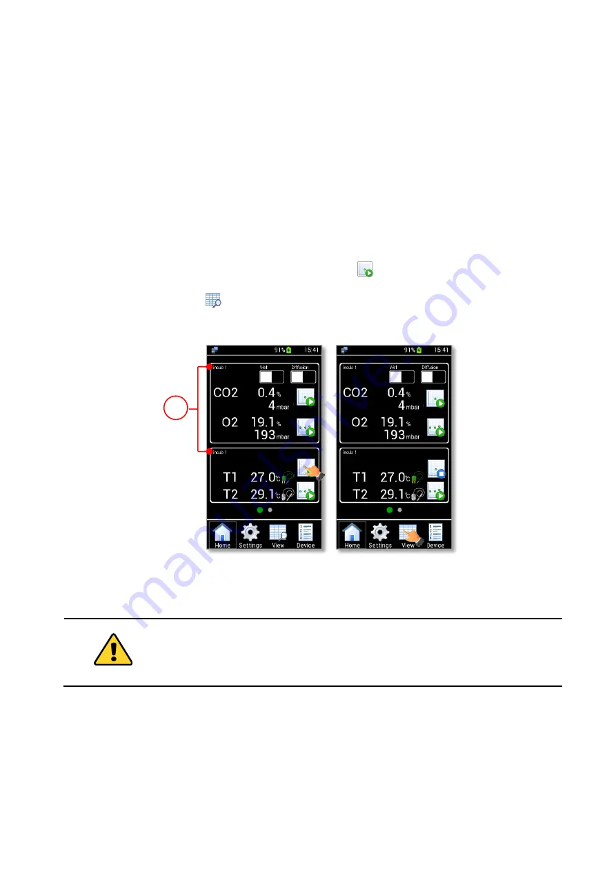
After connecting the temperature module (T1 or T2-MODULE), follow the instructions below to start a 

temperature Single Point Measurement. 

1.


Select the Device for which data has to be stored (see paragraph 9.3.1).  

Note


 If no device is selected, the data is stored on the current device shown on the home page (1 in Figure 

55 a). 

Tip


 During a gas measurement, you can start a temperature measurement and select a different Device 

for which temperature data shall be stored.  

2.


Wait until the temperature reading becomes stable. 

3.


Press the Temperature Single Point Measurement icon 

 (see Figure 55 a). 

4.


Press the View icon 

 to view stored data (see Figure 55 b). More details are reported in chapter 

12. 


Figure 55. Homepage during a temperature single point measurement. 


Before clicking on  Single  Point  Temperature Measurement,  wait for  reading temperature is 
stable. 


11.3


Temperature Logging 

To start a temperature logging follow the instructions below: 

1.


Select the Device for which the data have to be stored (see paragraph 9.3.1).  

Completed

a

b

1

No Measure

No Measure

Single point

Summary of Contents for LEO

Page 1: ...LEO Handheld Analyzer for IVF Applications Manual IST1446_REV05 SV 3 1 64 0 ...

Page 2: ...This page was left blank ...

Page 3: ... TUBES 11 5 10 CO2 O2 MODULE EMBEDDED IN LEO 11 5 11 PUMP EMBEDDED IN LEO 11 6 OPTIONAL PARTS 13 6 1 T1 MODULE 13 6 2 T2 MODULE 13 7 LEO CONNECTION PORTS 14 8 PRELIMINARY OPERATIONS 15 8 1 CHARGE THE BATTERY 15 8 2 DATE TIME SETTING 16 8 3 MEMORY CHECK 16 9 NAVIGATION MENU 17 9 1 HOMEPAGE 17 9 2 ALARM ICONS AND MEANINGS 19 9 3 SETTINGS 19 9 3 1 Device 20 9 3 2 Calibration 21 9 3 3 Pump 22 9 3 3 1 ...

Page 4: ...2 1 1 Span Gas Cylinder with Pressure Regulator 59 13 2 1 2 Span Gas Cylinder with Flow Regulator 60 13 2 2 CO2 O2 User Calibration with Certified Gas at atmospheric pressure Preliminary Operations 61 13 2 3 Span Setting 62 13 2 4 Start 64 13 2 4 1 Auto Gas calibration 64 13 2 4 2 Manual Gas Calibration 65 13 3 FACTORY 66 13 4 CO2 ZERO RESET 67 13 4 1 CO2 Zero Reset with Air 68 13 4 2 CO2 Zero Res...

Page 5: ...ou with helpful suggestions Note Supplies you with important information to successfully use the instrument 1 2 Symbols on the product label CE MARKING This symbol indicates the product s compliance with EU legislation PRODUCT DISPOSAL this symbol indicates that this product must not be disposed as urban solid waste This symbol indicates the product production date This symbol indicates the Manufa...

Page 6: ...d damage the device and its accessories Do not exceed the voltages indicated in this manual or on the product label Avoid excessive induction noise static electricity or magnetic fields Do not expose this instrument to water or moisture Avoid throttling and kinking of tubes Check tubing from time to time for possible wear and tear Check that all tubing is fully inserted into connectors and secure ...

Page 7: ...e product meets the technical requirement of the Directive 2011 65 EU Restriction of the use of certain hazardous substances RoHS The product has been tested according to European Standard EN 50581 2012 Technical documentation for the assessment of the electrical and electronic products with respect to the restriction of hazardous substances 3 2 Waste Electrical and Electronic Equipment Directive ...

Page 8: ... Moreover sensor calibration can be performed by using LEO intuitive user calibration routines LEO works in Diffusion Mode when the gas to be sampled is pressurized and in Aspiration Mode when it works at atmosphere pressure sucking the gas from the incubator by an internal pump In both cases if the gas inside the incubator is humid prior de humidification with the Moisture Trap included standard ...

Page 9: ...Sensor Modules see paragraph 10 and paragraph 13 4 CO2 O2 MODULE embedded into LEO T1 MODULE external T2 MODULE external CO2 PPM MODULE external HUMIDITY MODULE external FLOW RATE MODULE external Figure 2 LEO with T1 MODULE and T2 MODULE ...

Page 10: ...lab com for more details A B C D G H F E I J K L M Figure 3 LEO Hard Case A LEO Hand held meter for IVF applications B Power Supply see paragraph 5 1 C USB Cable D Soda Lime Kit see paragraph 5 2 E Moisture Trap for humid gas measurement see paragraph 5 3 F Filter G OTG Cable see paragraph 5 4 H Lanyard I Fitting Tubes see paragraph 5 5 J Tube B see paragraph 5 8 K Tube A see paragraph 5 7 ...

Page 11: ... with the device for charging the battery from a power outlet Connect the USB cable between the LEO MICRO USB port and the power adapter to charge the internal battery in LEO see Figure 4 MICRO USB PORT USB CABLE POWER ADAPTER Connect to a live electrical outlet Figure 4 LEO connection for battery recharging Figure 5 Power Adapters supplied ...

Page 12: ...oisture Trap E in Figure 3 is used for humid gas measurements Figure 7 shows the Moisture Trap components 1 A condensation trap allowing for the reduction of sampled gas temperature and the collection of condensed water from the sampled gas 4 in Figure 7 The condensation trap top 3 in Figure 7 allowing reducing the sampling gas time during the Single Point measurement must be removed when Gas Logg...

Page 13: ...es 1 from ID 1 6mm to ID 3 2mm 2 from ID 2 4mm to ID 3 2mm 3 from ID 4 0mm to ID 3 2mm 4 from ID 4 8mm to ID 3 2mm 5 from ID 6 4mm to ID 3 2mm Three additional caps for LEO s ports a male and female luer connector have been also supplied Note Additional caps are used to perform the Leak test of the pump see paragraph 9 3 3 1 5 6 Calibration Kit The Calibration Kit L in Figure 3 allows calibration ...

Page 14: ... Tube B 1 in Figure 11 when sampling a dry gas or to the Gas Outlet connector labeled green of the Moisture Trap 1 Figure 7 when sampling a humid gas The clear connector of Tube A 3 in Figure 10 must be connected to one of the Gas Inlet connector of LEO see Figure 46 for the measurement in Diffusion Mode or Figure 48 for the measurements in Aspiration mode A hydrophobic filter 2 in Figure 10 is fi...

Page 15: ...ure in the units of mbar psi and KPa CO2 O2 MODULE is temperature and pressure compensated thanks to a dedicated temperature and pressure sensor that are included in this module The CO2 O2 MODULE is factory calibrated by using traceable standards and stores the calibration data in its internal memory The declared accuracy is guaranteed for a period of 6 months from the factory calibration date The...

Page 16: ...12 Figure 13 Pump ...

Page 17: ...EO see paragraph 12 Figure 14 T1 MODULE Note Okolab recommends that the T1 MODULE should be calibrated after one year of use 6 2 T2 MODULE The T2 MODULE see Figure 15 is a calibrated temperature probe that can be read and displayed by LEO The T2 MODULE has an external diameter of 2 mm and it s suitable for temperature measurements of benchtop and hightop incubators where the temperature monitoring...

Page 18: ...paragraph 15 Press and hold for 10 seconds the power button to restart LEO Press the power button to lock and unlock LEO s screen during the use Press the power button to display the battery charging status see paragraph 8 1 2 MICRO USB port To charge the battery with the power adapter see paragraph 5 1 and to download software updates 3 Gas input port labeled with icon 4 Gas input port labeled wi...

Page 19: ...harging symbol appears at the top of the LEO display 1 in Figure 17 The percentage of battery charge shows besides the battery symbol 2 in Figure 17 When charging is complete the Battery full symbol appears at the top of display v 1 2 Figure 17 Homepage battery If LEO is switched off press the power button to display the battery charging status and the percentage of battery charge see Figure 18 ...

Page 20: ...her than 90 8 2 Date Time setting When turning LEO on for the first time Date Time have to be set because the current date time values are stored with every reading To change Date Time and their format see paragraph 9 3 5 1 8 3 Memory Check When you want to use LEO for a large number of measures Okolab recommends checking the system memory LEO has a memory page where the stored records and the sti...

Page 21: ...ent to start a Single Point measurement of CO2 O2 gas concentration See paragraph 10 1 3 4 CO2 O2 Logging to start a Logging of CO2 O2 gas concentration See paragraph 10 1 4 5 Temperature Single Point Measurement to start a Single Point temperature measurement See paragraph 11 2 If no Temperature sensor is connected to LEO this function does not work 6 Temperature Logging to start a temperature lo...

Page 22: ...ment One of the following five options will be displayed NO measure if no CO2 O2 measurement is in progress Single point if a single point gas measurement is in progress Logging if a CO2 O2 Logging is in progress Completed if a CO2 O2 measurement Logging is completed 19 Device name the name of the device for which data will be stored see paragraph 9 3 1 20 PC Icon PC connection 21 Alarm Icon Devic...

Page 23: ...s out of the range defined in the alarm subpage see paragraph 9 3 4 after the Transient Time The meter triggers in Alarm Tip If the temperature sensors are connected to LEO the Red Warning Alarm Icon appears next to T1 and or T2 during an alarm condition The Humidity Alarm Icon indicates that the current humidity value in LEO is higher than 80 for example the Moisture Trap is full The meter trigge...

Page 24: ...ice name for which data shall be stored see Figure 21 b When selecting an already existing device a pop up dialog box appears see Figure 21 c showing the three following options Use to use the selected device Edit to change the device name Delete to delete the device Figure 21 Device selection a b c Note When deleting a device all its data is erased too Note Default device cannot be deleted a b a ...

Page 25: ...ss Save You can add up to 40 devices Figure 22 How to add a new device a b 9 3 2 Calibration By pressing the Calibration icon as shown in Figure 23 a you can calibrate the available sensors and you can display stored calibration data a b Figure 23 Calibration page a b Note External sensor modules icons are automatically disabled if sensor modules are not connected to LEO a b ...

Page 26: ...ure 24 c Tip The default flow rate value is 150 ml min You can also reset the remaining lifetime if a new pump is installed by pressing on Reset see Figure 24 c See the paragraph 18 for the pump replacement Note The pump lifetime must be reset only if you replace the pump with a new one a b c Figure 24 Pump Page a b c 9 3 3 1 Pump Leak Test You can perform the Leak test to verify the proper functi...

Page 27: ...se additional caps supplied in LEO s Hard case 2 Put the cap on LEO gas inlet port with icon 2 in Figure 26 1 2 Figure 26 Put caps on LEO ports 3 Press on Continue see Figure 27 a The pump starts operating and aspirating air The pressure inside LEO begins to rise Wait until aspiration step is completed see Figure 27 b Figure 27 c appears a b c Figure 27 How to set Pump Leak Test aspiration step a ...

Page 28: ...ring this time the pump is not running Wait until the Leakage evaluation step is completed see Figure 29 c 3 Figure 28 Put the cap on LEO gas inlet port a b c Figure 29 How to set Pump Leak Test stabilization and Leakage evaluation steps a b c If the Leak test is passed the pump works properly The green label showing OK appears as in Figure 30 ...

Page 29: ... test during remote assistance session 9 3 4 Alarm Press the Alarm icon see Figure 31 a to enter the Alarm subpage You can set alarm parameters for each sensor by following the instructions below 1 Select the sensor you want to set alarm parameters for example CO2 see Figure 31 b 2 Insert the Minimum Min and Maximum Max value within which the measurements can be considered valid not in alarm see F...

Page 30: ...modules icons are automatically disabled if sensor modules are not connected to LEO 9 3 5 System Figure 32 b shows the System subpage Press the System icon see Figure 32 a to see or modify system options Date Time See paragraph 9 3 5 1 Power Saving See paragraph 9 3 5 2 Memory See paragraph 9 3 5 3 Info See paragraph 9 3 5 4 Figure 32 System page a b b c a a b ...

Page 31: ...ate Time configuration a b 2 Press Change see Figure 33 b to enter the Set Date page Tip Okolab recommends to check the Date Time Settings the first time you turn LEO on because the current Date Time values are stored with every reading 3 Change the date using and 1 2 3 in Figure 34 b Figure 34 Set Date a b 4 Press Save 4 in Figure 34 b to confirm a b ...

Page 32: ...36 a to set Low brightness feature and Stand By feature Low brightness feature is enabled by default Set the time period after which LEO will reduce the display s brightness by 15 Note Display s brightness is automatically reduced when the remaining battery power is less than 5 The Stand By feature is disabled by default Enable the Stand By feature by flag the checkbox Set the time out period afte...

Page 33: ...y see Figure 37 b Note Before starting to measure make sure that the space available on LEO memory is large enough to store new records Figure 37 Memory check a b 9 3 5 4 Info Press the icon to access the System Information as shown in Figure 38 a This page contains the information related to LEO serial number and version see Figure 38 b Click on the right arrow icon to move to sensor module infor...

Page 34: ...e Display icon to modify the display options see Figure 39 a As shown in Figure 39 b in the Display page it is possible to set Brightness to modify the display brightness see paragraph 9 3 6 1 Theme to modify the theme see paragraph 9 3 6 2 Touchscreen to modify the touch options see paragraph 9 3 6 3 Figure 39 Display settings a b a b ...

Page 35: ...ss Save to confirm or Cancel to undo Figure 40 Display settings Brightness a b Note Display s brightness is automatically reduced when the remaining battery power is less than 5 9 3 6 2 Theme To modify the display Theme press the icon see Figure 41 a and select the theme you prefer in the page that opens see Figure 41 b Figure 41 Display settings Theme a b a b a b ...

Page 36: ...ons a b Note To activate a sound at each touch flag the Touch Buzzer checkbox 2 in Figure 42 b 9 3 7 Units Press the Units icon see Figure 43 a to change the measurement units of temperature and pressure variables There are three available options for both temperature and pressure as shown in Figure 43 b Select the measurement unit you prefer to use and press Save to confirm 3 in Figure 43 b Tip T...

Page 37: ...ure 44 a to restore the default factory settings a pop up dialog box appears see Figure 44 b Press Ok to start Factory Reset or Cancel to undo see Figure 44 b Figure 44 Factory reset a b Note Factory Reset will erase user calibration of all sensor modules connected a b 1 2 3 a b ...

Page 38: ...50 ml min Aspiration Mode with pump running Use Aspiration Mode when the sampling gas is at atmospheric pressure Tip The default value of the gas flow rate sucked by LEO is 150 ml min To change this value see paragraph 9 3 3 To start a gas measurement process press the ON OFF button and wait until the Warming up time ends It will take 15 minutes for CO2 O2 MODULE to achieve stability During this t...

Page 39: ... sampling gas is humid connect the red connector of Tube A 3 in Figure 46 Configuration b and the green connector of Tube B 4 in Figure 46 Configuration b to the Moisture Trap In this case operate in Wet Mode see paragraph 10 1 5 4 Connect the end of Tube B to the incubator or to the point where measurement is required 4 in Figure 46 Configuration a and 5 in Figure 46 Configuration b 5 Okolab reco...

Page 40: ...tion a LEO connections in DiffusionMode To dry incubator TUBE A 6 3 2 1 5 To wet incubator TUBE B TUBE B Configuration b LEO connections in DiffusionMode 4 Figure 46 LEO Connections in Diffusion Mode Configuration a Configuration b ...

Page 41: ...8 Configuration a If the sampling gas is humid connect the red connector of Tube A 3 in Figure 48 Configuration b and the green connector of Tube B 4 in Figure 48 Configuration b to the Moisture Trap In this case operate in Wet Mode see paragraph 10 1 5 4 Connect the end of Tube B to the incubator or to the point where measurement is required 4 in Figure 48 Configuration a and 5 in Figure 48 Confi...

Page 42: ...n a LEO connections in Aspiration Mode To dry incubator 2 TUBE B TUBE A 6 3 1 5 To wet incubator TUBE B Configuration b LEO connections in Aspiration Mode 4 Figure 48 LEO Connections in Aspiration Mode Configuration a Configuration b ...

Page 43: ...raph 9 3 1 Note If no device is selected the data will be stored on the current device shown on the Homepage 1 in Figure 50 a 2 Press the CO2 O2 Single Point Measurement icon see Figure 50 a A pop up dialog box appears see Figure 50 b Select Auto for an automatic or Manual for a manual measurement Auto the CO2 O2 Single Point measurement terminates automatically when the gas reading value becomes ...

Page 44: ...O2 O2 Single Point Measurement icon becomes see Figure 50 c 3 Press the View icon to view data stored see Figure 51 a More details are reported in chapter 12 b a Figure 51 View data stored a b c 10 1 4 CO2 O2 Logging To start a CO2 O2 Logging follow the instructions below 1 Select the Device for which the data have to be stored see paragraph 9 3 1 b c a 1 2 ...

Page 45: ...O2 and O2 concentration 4 in Figure 52 b Then press Start to start the measurement 5 in Figure 52 b Note If CO2 and or O2 check boxes are enabled see Figure 52 b the alarm triggers when the reading concentrations values are out of the set range See paragraph 9 3 4 to set the gas alarm range Note The Pump Run Time CANNOT be less than 1 min Note If the time inserted in Each is less than the Pump Tim...

Page 46: ...raph 10 1 the loss of water molecules changes the composition of the gas and has an effect on the CO2 O2 measurement To address this issue and correct the CO2 and O2 measurement to account for the incubator real condition you can use the Wet Mode The Wet Mode is a LEO feature allowing you to set the incubator temperature and relative humidity values LEO will correct the CO2 and O2 values by accoun...

Page 47: ...rature value is immediately shown 2 Connect T2 MODULE or T1 MODULE to the other probe connector for a simultaneous T1 and T2 temperature measurement see Figure 54 b The reading temperature value is immediately shown 3 Introduce the T1 probe or T2 probe into the temperature monitoring port of the incubator 4 Wait for LEO starts reading a temperature value The reading is shown on the homepage to the...

Page 48: ...erent Device for which temperature data shall be stored 2 Wait until the temperature reading becomes stable 3 Press the Temperature Single Point Measurement icon see Figure 55 a 4 Press the View icon to view stored data see Figure 55 b More details are reported in chapter 12 Figure 55 Homepage during a temperature single point measurement Before clicking on Single Point Temperature Measurement wai...

Page 49: ...s For the time interval of the Temperature Logging The time can be inserted in hours and minutes 5 Enable Disable the alarm on T1 and or T2 1 in Figure 56 c and then press Start to start the measurement 2 in in Figure 56 c Note If T1 and or T2 check boxes are enabled see Figure 56 c the alarm triggers when the reading temperature values are out of the set range See paragraph 9 3 4 to set the tempe...

Page 50: ...46 Figure 57 Temperature logging view data 6 Press the View icon to view the data stored see Figure 57 b More details are reported in chapter 12 Completed a b Completed Completed 1 ...

Page 51: ...sensor module 2 Use the UP and DOWN arrows to scroll the device list 1 in Figure 58 b 3 Use the LEFT and RIGHT arrows to view the measurements by date 2 in Figure 58 b 4 Press the icon 3 in Figure 58 b to select the variables to see download or delete Flag the variables and then press OK button to save see Figure 58 c Note You can display up to 4 variables at any one time b a c 1 2 3 Figure 58 How...

Page 52: ...easurement The number of the measurements depends on whether you started a single point measurement or a gas temperature logging For single point measurement LEO shows 1 3 in Figure 60 and the time when the measurement is over 2 in Figure 60 For a gas temperature logging LEO shows a number that depends on the values inserted for Each and For parameters before starting the measurement see paragraph...

Page 53: ...hey are shown in the top right of the page 4 in Figure 59 c In the example reported in Figure 59 c the CO2 alarm parameters set before starting the measurement are 1 0 as CO2 minimum Min and 7 2 as CO2 maximum Max values 12 2 Downloading Data LEO is equipped with local memory to store sensor modules readings These data can be downloaded on a USB flash drive on user request To download the stored d...

Page 54: ...e Figure 64 a 3 Press the icon to access to the Download Delete Data page see Figure 64 b 4 Insert the start time and the end time corresponding to the data interval to download 1 and 2 in Figure 64 c 5 Enable the Download check box to download the selected data 3 in Figure 64 c Then press OK to download data to the USB key 4 in Figure 64 c 1 ...

Page 55: ...gure 65 Figure 65 How to download all data stored on LEO To download all the readings of a single device connect the USB key to the MINI USB port see Figure 62 and follow the instructions below 1 Press the View icon to open the View Data page see Figure 64 a 2 Press the device name see Figure 66 a 3 Press the icon see Figure 66 b in the page that opens A pop up dialog box appears b a c 4 1 2 3 1 3...

Page 56: ... of a single device connect the USB key to the MINI USB port see Figure 62 and follow the instructions below 1 Press the device name see Figure 59 a 2 Press a single reading see Figure 59 b and then press the icon see Figure 67 a in the page that opens A pop up dialog box appears 3 Enable the Download check box 1 in Figure 67 a and then press OK to download the selected data to the USB Key 2 in Fi...

Page 57: ...ed in the USB drive as shown in Figure 68 Figure 68 Downloaded files on the pen drive Tip Please use Microsoft Excel to open the downloaded txt files You can download LEO DATA IMPORT Excel Macro from Okolab website www oko lab com LEO DATA IMPORT Excel Macro helps you to organize your stored data ...

Page 58: ... To delete the stored data follow the instructions below 1 Press the View icon see Figure 70 a the View Data page opens see Figure 70 b 2 Press the icon see Figure 70 b to access the Download Delete page 3 Insert the start time and the end time corresponding to the data interval to delete 1 and 2 in Figure 70 c 4 Enable the Delete check box to delete the selected data 3 in Figure 70 c Then press O...

Page 59: ...ngs of a single device follow the instructions below 1 Press the View icon to open the View Data page see Figure 70 a 2 Press the device name see Figure 72 a 3 Press the icon see Figure 72 b in the page that opens A pop up dialog box appears 4 Enable the Delete check box 1 in Figure 72 c and then press OK to download the selected data to the USB Key 2 in Figure 72 c Figure 72 How to Delete Data fo...

Page 60: ...see Figure 73 b A pop up dialog box appears 3 Enable the Delete check box 1 in Figure 73 c and then press OK to delete the selected data 2 in Figure 73 b a b 1 2 c Figure 73 How to Download Data for a single reading a b Tip You can download and delete simultaneously collected data by enabling both Download and Delete checkboxes as shown in Figure 74 Figure 74 How to Delete and Download Data simult...

Page 61: ... a b c Figure 76 CO2 O2 Calibration page CO2 O2 Calibration page contains five subpages View Current to view factory calibration or CO2 O2 User Calibration data See paragraph 13 1 Span Calibr to run CO2 O2 User Calibration using certified span gas See paragraph 13 2 Note Span gas is a gas mixture of precisely defined composition used as reference gas in the calibration of gas meters Calibration is...

Page 62: ...he example shown in Figure 77 b and c a b c Figure 77 CO2 O2 View Calibration a b c The recommended CO2 O2 MODULE calibration interval is six months However Okolab suggests to verify LEO s reading each month or before each important measurement by employing a certified span gas To achieve the best accuracy perform the gas measurement immediately after the CO2 O2 User Calibration 13 2 Span Calibrat...

Page 63: ...ollow the instructions below to connect LEO to the span gas cylinder equipped whit a pressure regulator 1 Connect the clear connector of Tube A to LEO gas inlet port with icon 1 in Figure 79 2 Put the cap on LEO gas inlet port with icon 2 in Figure 79 3 Connect the clear connector of the Calibration Kit to red connector of Tube A 3 in Figure 79 Figure 78 Calibration Kit connected to Tube A 4 Conne...

Page 64: ...re 59 3 Connect the red connector of the Tube A to the green connector of Tube B 3 in Figure 59 4 Connect the end of Tube B to the span gas cylinder regulator 4 in Figure 59 Tip Use the fitting tubes or additional tubes in order to allow the compatibility of the supplied tubing with the gas port of your gas cylinders 5 Okolab recommends the use of a purge tube attached to LEO gas outlet port 5 in ...

Page 65: ...ion with a gas at atmospheric pressure by using the Tube A Follow the instructions below to connect LEO to Tube A 1 Connect the clear connector a of the Tube A to LEO gas inlet port labeled with icon 1 in Figure 81 2 Put the cap on LEO gas inlet port labeled with icon 2 in Figure 81 3 Connect the red connector b of Tube A to the gas reference at atmospheric pressure 1 in Figure 81 4 Okolab recomme...

Page 66: ...Setting Press Span Calibration icon to access to the Span Calibration submenu see Figure 82 a a b Figure 82 Span gas setting page a b To set all parameters of the span gas used to calibrate the CO2 O2 MODULE follow the instructions below 1 Press Span Setting icon in the page that opens see Figure 82 b to access to the Span Settings page ...

Page 67: ... a span calibration by two span gases Span Gas 1 and Span Gas 3 during the procedure the Span Gas 1 will be used for calibrating both sensors CO2 at 6 00 and O2 at 5 00 the Span Gas 3 only for calibrating the CO2 sensor at 19 a b Figure 83 Span Settings page a b 3 If you use a gas with an overpressure for the CO2 O2 User Calibration you can calibrate LEO in Diffusion Mode as shown in Figure 83 b 4...

Page 68: ...ion a b Figure 85 Span gas start a b 13 2 4 1 Auto Gas calibration By pressing on Auto in Figure 85 b Figure 86 a appears Press Continue see Figure 86 a to start the Span Calibration after checked the proper span gas cylinder is connected to LEO During an Auto calibration you can see CO2 and O2 readings on the display see Figure 86 b Wait until CO2 O2 User Calibration is completed for the first sp...

Page 69: ...ompleted 13 2 4 2 Manual Gas Calibration By pressing on Manual in Figure 85 b Figure 88 a appears Press Continue see Figure 88 a to start the Span Calibration after checking that the proper span gas cylinder is connected to LEO During a Manual calibration you can see the CO2 and O2 readings on the display Wait until the CO2 and O2 readings became stable Tip Okolab suggests waiting at least 10 minu...

Page 70: ... 88 How to set Manual Gas Calibration a b c View Current icon to view the CO2 O2 User Calibration data 13 3 Factory LEO allows to delete the last CO2 O2 User Calibration and to restore the factory values To reset the current sensors calibration 5 Press the Factory icon see Figure 89 a 6 Flag the checkbox of the variables for which you want to delete the CO2 O2 User Calibration see Figure 89 b Tip ...

Page 71: ...O will remind you every thirty days to perform the CO2 Zero Rest before the CO2 O2 User Calibration and before a CO2 single or logging measurement see Figure 90 b a b Figure 90 LEO warning messages suggesting the CO2 Zero Reset a b Note After thirty days from the last CO2 Zero Reset you must perform the CO2 Zero Rest before the CO2 O2 User Calibration Note After thirty days from the last CO2 Zero ...

Page 72: ... b Figure 91 CO2 Zero Reset a b 13 4 1 CO2 Zero Reset with Air Press on Air to start the CO2 Zero Reset if you are using air See Figure 92 a a b c Figure 92 CO2 Zero Reset with Air a b c Pressing on Air LEO reminds you to connect the Soda Lime kit Figure 92 b To connect the Soda Lime Kit to LEO follow the instructions below 1 Connect the clear connector of Tube A to LEO gas inlet port labeled with...

Page 73: ...a Lime kit has to be replaced when the Soda Lime filter changes color turning purple Contact Okolab to purchase a new Soda Lime kit TUBE A Soda Lime Kit 1 2 3 Figure 94 How to connect LEO during a CO2 Zero Reset procedure with Air The CO2 Zero Reset procedure takes 15 minutes the remaining time is shown on the display during the procedure see Figure 92 c At the end of the CO2 Zero Reset procedure ...

Page 74: ...at the CO2 Zero Reset procedure and if it fails again please contact Okolab support at support oko lab com Figure 96 CO2 Zero Reset procedure with Air has failed 13 4 2 CO2 Zero Reset with N2 To start the CO2 Zero Reset procedure using N2 press on N2 as shown in Figure 97 a Pressing on N2 LEO reminds you to connect a Nitrogen bottle at 1 0 barg 14 5 psig to LEO See Figure 97 b ...

Page 75: ...e end the Calibration Kit to red connector of Tube A 3 in Figure 99 Figure 98 Calibration Kit connected to Tube A 4 Connect end of the Calibration Kit to the gas cylinder 4 in Figure 99 5 Okolab recommends the use of a purge tube attached to LEO gas outlet port 5 in Figure 99 The purge tube has to be placed in a well ventilated environment You can use the supplied additional tube as tube for purgi...

Page 76: ...ect the red connector of the Tube A to the green connector of Tube B 3 in Figure 100 4 Connect the end of Tube B to gas cylinder regulator 4 in Figure 100 Tip Use the fitting tubes see paragraph 5 5 in order to allow the compatibility of the supplied tubing with the gas port of your gas cylinders 5 Okolab recommends the use of a purge tube attached to LEO gas outlet port 5 in Figure 100 The purge ...

Page 77: ...he end of the CO2 Zero Reset procedure with N2 a pop up message is shown as in Figure 101 Press Ok to return to the CO2 O2 Calibration page Figure 101 CO2 Zero Reset procedure with N2 completed If the CO2 Zero Reset procedure has failed the message shown in Figure 102 appears In this case Okolab recommends to repeat the CO2 Zero Reset procedure and if it fails again please contact Okolab support a...

Page 78: ...1 Connect the external gas meter to the incubator in order to read the CO2 and O2 compositions inside the incubator see Figure 103 Figure 103 External gas meter connection to the incubator Once you have connected the external gas meter to the incubator wait until it steadily reads CO2 and O2 values and make sure that the system remains stable over time and the incubator is closed When External Gas...

Page 79: ...nd O2 concentrations see paragraph 10 1 3 3 Calculate the CO2 O2 Offset value Offset as the difference between CO2 O2 concentration read by the external gas meter Reference and the concentration read by LEO LEO Reading Note that also negative values are acceptable 4 Insert the CO2 O2 Offset calculated value Offset in Offset box as shown in Figure 104 a b Figure 104 How to insert CO2 O2 Offset valu...

Page 80: ...76 Figure 105 How to insert CO2 O2 Reference value a b Note When you start the CO2 O2 User Calibration procedure LEO deletes all stored Offset values ...

Page 81: ...r T2 Calibration page see Figure 106 b T1 Calibration page T2 Calibration page contains three subpages see Figure 106 c View To view the factory calibration data or verify if there are offsets on the temperature Start To calibrate the temperature sensor using a calibration procedure Tip You can set until to five temperature values as points for the calibration procedure Factory Reset To cancel the...

Page 82: ... water bath 3 Set the water bath to the calibration temperature and wait for the temperature stability 4 Press Start icon see Figure 108 a 5 Insert the temperature read by the temperature reference in Certified Temperature as shown in Figure 108 b 6 Press Set 2 in Figure 108 b to save the calibration point Tip You can define up to five temperature points so you may set the water at any 5 different...

Page 83: ...ave to complete the calibration or Cancel to undo Figure 109 T1 Multi Point Calibration 14 3 Factory Calibration Press Factory Reset icon to cancel the last user temperature calibration and restore the factory values see Figure 110 a If you are sure of the reset press OK as shown in Figure 110 b 36 8 2 b a c 36 8 1 2 25 00 30 00 37 00 40 00 50 00 ...

Page 84: ...80 Figure 110 T1 Calibration Factory Reset a b b a ...

Page 85: ...ation see Figure 111 While holding the ON OFF button the pop up message shown in Figure 112 a appears Tap the blue calibration dots until the calibration is complete see Figure 112 b Figure 111 How to enter in Touchscreen Calibration Figure 112 Start the Touchscreen Calibration a b Front view Right view b a ...

Page 86: ...for gas measurement without the filter Okolab recommends changing hydrophobic filters every three months The CO2 O2 MODULE should be factory calibrated every year and verified by the user each month or before of each important measurement To calibrate CO2 O2 MODULE it has to be extracted from LEO To extract the CO2 O2 MODULE see paragraph 17 The Internal Pump has lifetime of 1000 hours of LEO oper...

Page 87: ...ws 1 in Figure 113 c and 2 in Figure 113 d by using a hexagonal key 1 5 mm 3 Disconnect inlet see Figure 113 e and outlet tube see Figure 113 f from the CO2 O2 MODULE Then lift up and remove the CO2 O2 MODULE a b c e f d 2 1 1 Figure 113 CO2 O2 MODULE extraction Follow the instructions below to insert the new CO2 O2 MODULE 4 Connect inlet see Figure 114 a and outlet tube see Figure 114 b to CO2 O2...

Page 88: ...84 f e c a b d 2 1 1 Figure 114 CO2 O2 MODULE insertion ...

Page 89: ... LEO see Figure 115 b 2 Loosen the screws 1 in Figure 115 c and 2 in Figure 115 d by using a hexagonal key 1 5 mm 3 Disconnect inlet see Figure 115 e and outlet tube see Figure 115 f from the CO2 O2 MODULE Then lift up and remove the CO2 O2 MODULE a b c e f d 2 1 1 Figure 115 CO2 O2 MODULE extraction before pump replacement Follow the instructions below to replace the pump 1 Loosen the screw as sh...

Page 90: ...lace the pump with new pump ordered from Okolab 5 Reconnect the electrical connector of the new pump see Figure 117 a 6 Connect the inlet and outlet tubes see Figure 117 b Connect LEO tube marked by see Figure 117 c to the inlet port of the pump 1 in Figure 117 d Connect LEO tube marked by see Figure 117 c to the outlet port of the pump 2 in Figure 117 d 7 Place the pump in its slot see Figure 117...

Page 91: ...CO2 O2 MODULE 1 Connect inlet see Figure 118 a and outlet tube see Figure 118 b to CO2 O2 MODULE 2 Fasten the screws 1 in Figure 118 c and 2 in Figure 118 d by using a hexagonal key 1 5mm 3 Put the rear cover on LEO and fasten the screw by using a hexagonal key 2 5mm as shown in Figure 118 f ...

Page 92: ...88 f e c a b d 2 1 1 Figure 118 CO2 O2 MODULE insertion after pump replacement ...

Page 93: ...tate to contact Okolab for any further commercial information or technical support For HARDWARE SUPPORT sibillo oko lab com Phone 39 081 806 3470 Fax 39 081 876 4410 Mobile 39 348 96807 18 For COMMERCIAL SUPPORT WORLDWIDE lanzaro oko lab com Phone 39 081 806 2624 Fax 39 081 876 4410 Mobile 39 348 96807 17 For COMMERCIAL SUPPORT US CANADA foppiano oko lab com For COMMERCIAL SUPPORT CHINA tong oko l...

Page 94: ... save data before erasing Humidity Alarm Possible Moisture Trap absence or wrong connections Please verify that Moisture Trap is properly connected High O2 level and low CO2 level in measurement Possible air infiltration Wrong Connections Verify that all the connectors are correctly plugged on LEO and eventually on Moisture Trap Verify that Tube B is properly connected on incubator eventually usin...

Page 95: ...300 measurements Data Download Micro USB to USB OTG host adapter Visual and audio alarm Selectable for each sensor module Dimensions 95x155x45 mm Weight 492 g Power Consumption 10 W Power Supply 5V DC Environmental Conditions Temperature range 5 C 40 C Relative Humidity 0 95 Barometric Pressure 800 1200 mbar Pump Pump type Micro Diaphragm Pump Pump Flow From 60 to 260 ml min Pump Life Expectancy 1...

Page 96: ... Reading in the range 0 10 1 2 of Full Scale 3 Reading in the range 11 20 1 Response Time T90 35 s O2 Sensor Technical Data Sensor type Fluorescence based optical sensor Measurement Range 0 25 Accuracy 1 of Full Scale in the range 0 10 1 2 of Full Scale 3 Reading in the range 11 25 1 Response Time T90 35 s 1 Reference Condition 1000 mbar and 23 C ...

Page 97: ...h 2m OD 0 13mm Range 0 60 C Accuracy from 20 to 50 C 0 1 C Figure 119 T1 MODULE Technical drawing 21 4 T2 MODULE Technical Data Sensor PT1000 RTD Class A Probe Length 150mm OD 2 0mm Cable Length 1m Range 0 60 C Accuracy from 20 to 50 C 0 1 C Figure 120 T2 MODULE Technical drawing ...

Page 98: ... 27 Figure 34 Set Date a b 27 Figure 35 Set Time a b 28 Figure 36 Power saving settings a b 29 Figure 37 Memory check a b 29 Figure 38 System information a b 30 Figure 39 Display settings a b 30 Figure 40 Display settings Brightness a b 31 Figure 41 Display settings Theme a b 31 Figure 42 Display settings Touchscreen options a b 32 Figure 43 Units a b 33 Figure 44 Factory reset a b 33 Figure 45 LE...

Page 99: ...2 Zero Reset a b 68 Figure 92 CO2 Zero Reset with Air a b c 68 Figure 93 Soda Lime Kit connected to Tube A 69 Figure 94 How to connect LEO during a CO2 Zero Reset procedure with Air 69 Figure 95 CO2 Zero Reset procedure with Air completed 70 Figure 96 CO2 Zero Reset procedure with Air has failed 70 Figure 97 CO2 Zero Reset on N2 a b c 71 Figure 98 Calibration Kit connected to Tube A 71 Figure 99 H...

Page 100: ...n Table Revision Number Addition of changes Date 01 Redaction June 2018 02 Review July 2018 03 New redaction November 2018 04 New features May 2019 05 Changes in hardware September 2019 06 Changes in tubes October 2019 ...

Page 101: ...kolab S r l neither assumes responsibility for any omissions or errors nor assumes liability for any damage that may results from improper use of its products in accordance with information provided by Okolab S r l Okolab S r l warrants only the parts manufactured by Okolab S r l to be free of defects Okolab S r l makes no other warranties or representations of any kind whatsoever express or impli...

Reviews: