background image

AH6 Robot Maintenance Manual   

Document Version V1.1.2 (19/09/2022)         

                                                                                                                            19 

Chapter 3


Handling of Common Exceptions 

Common  exceptions  in  mechanical  and  electrical  components  of  AH6  Robot  during 

installation and maintenance are shown in the table below. In case of an error code of the 

robot control system, refer to the "QKM Robot Error Code Manual" to check whether there 

is an exception in the system. If the exceptions described in the following table cannot be 

eliminated by mechanical ways, please contact QKM for technical support. 

Table 3-1 Handling of common exceptions 

Common Exception 

Possible Cause 

Handling 

Robot is in emergency 

stop state. 

Failure in robot 

emergency stop line. 


Ensure  that  the  emergency  stop 

switch is not pressed. 


Check  whether  the  emergency  stop 

switch is damaged. 


Replace the emergency stop switch. 

Unable to connect 

robot. 

Failure in PC network 

settings. 


Change  the  IP  of  the  PC  connected 

to  the  robot  to  be  in  the  same 

network  segment  as  the  robot's  IP, 

and then connect it. 

Multiple problems in PC  Disable all other network cards in the PC 

Summary of Contents for AH6

Page 1: ...AH6 Robot Maintenance Manual Document Version V1 1 2 19 09 2022 I...

Page 2: ...enance Manual AH6 Robot AH6 0500 0204 2000 AH6 0500 0204 3000 AH6 0600 0204 2000 AH6 0600 0204 3000 AH6 0700 0204 2000 AH6 0700 0204 3000 Version V1 1 2 Issue Date 19 09 2022 QKM Technology Dongguan C...

Page 3: ...lectrical components so that users can better use AH3 Robot This manual can serve as a reference for system integrators to design user workstation systems by using our AH3 Robot and can also be used t...

Page 4: ...personal injuries or deaths if it is not avoided It indicates that a potentially dangerous situation would occur and cause personal injury or robot damage if it is not avoided It indicates that an unp...

Page 5: ...rts Notice The contents of this document are subject to change any time due to product upgrade or other reasons QKM reserves the right to change the contents of maintenance and operation in this manua...

Page 6: ...gy Dongguan Co Ltd Headquarters Tower A Building 17 Headquarters 1 No 4 Xinzhu Road Songshan Lake High tech Industrial Development Zone Dongguan City Guangdong Province China Tel 86 0769 27231381 Fax...

Page 7: ...document was released V1 1 0 05 13 2020 Section 4 3 Replacement and maintenance of controller fan was deleted Section 4 5 Removal and installation of the second mechanical arm shell was added Section...

Page 8: ...added 4 Section 5 4 Description of surge PCBA interfaces and cable identification was added 5 Section 5 5 Description of filter interfaces and cable identification was added 6 Section 5 6 Description...

Page 9: ...10 2021 The maintenance detection of synchronous belt is added in Section 2 2 Corrected IO free distribution PCBA diagram in section 5 3 V1 1 2 19 09 2022 Modify the content of safety shutdown in cha...

Page 10: ...Table XV Chapter 1 Safety Precautions 1 1 1 Safety responsibility 1 1 2 Safety Precautions 2 1 2 1 Precautions for general safety 2 1 2 2 Precautions before robot operation 4 1 2 3 Precautions when op...

Page 11: ...nce standard 15 2 2 2 Transmission belt tension parameters 17 Chapter 3 Handling of Common Exceptions 19 Chapter 4 Maintenance of Mechanical Components 21 4 1 Lubrication of spline screw shaft 21 4 2...

Page 12: ...ce of surge protection PCBA 51 5 5 Replacement and maintenance of filter 54 5 6 Replacement and maintenance of QBUS module 56 5 7 Replacement and maintenance of QBUS fuse 58 5 8 Replacement and mainte...

Page 13: ...ation of side door panel 28 Figure 4 8 Upper control cabinet interface panel 29 Figure 4 9 Removal of upper control cabinet interface panel 30 Figure 4 10 Installation of upper control cabinet interfa...

Page 14: ...ee distribution PCBA 49 Figure 5 8 Removal of IO free distribution PCBA 50 Figure 5 9 Surge protection PCBA 52 Figure 5 10 Removal of fastening screws 53 Figure 5 11 Filter 54 Figure 5 12 Removal of f...

Page 15: ...AH6 Robot Maintenance Manual Document Version V1 1 2 19 09 2022 XV List of Table Table 1 1 Warning signs 9 Table 3 1 Handling of common exceptions 19 Table 4 1 Selection of lubricating grease 22...

Page 16: ......

Page 17: ...ed personnel are those who have received safety training on knowledge operation teaching etc of industrial robots knowledge related to inspection and other operations and related laws and regulations...

Page 18: ...hanges to the robot QKM is committed to providing safe and reliable information but does not assume responsibility for it Even if all operations are performed in accordance with the safety instruction...

Page 19: ...ot is not used Be sure to connect the cable_POWER to the power socket when using the robot Do not connect directly to the main power supply from factory Be sure to make replacement after turning off t...

Page 20: ...The protective area must be larger than the work area outside which protective devices need to be placed for warning and safe use Common isolated protective device safety fence common safety reminder...

Page 21: ...off state The supporting equipment such as jigs at the end of robot arms or other devices of the robot may cause danger and must be connected to the emergency stop circuit of the robot 1 2 3 Precauti...

Page 22: ...cation cables during normal operation of the robot 1 2 4 Precautions when a fault occurs When the robot fails be sure to operate it in accordance with normal steps to prevent personnel injury and robo...

Page 23: ...ing the robot The parts screws etc removed shall be correctly installed in their original positions In case of redundant or insufficient parts please confirm again and install them correctly When rest...

Page 24: ...he system speed 10 speed is recommended and then gradually increasing the speed after confirming that there is no problem After repairing and maintaining the robot test the robot to ensure that the ro...

Page 25: ...at an interval of about 1 min Do not restart it immediately after turning off the power to avoid damage to the robot Before the robot starts again check whether the emergency stop button is released...

Page 26: ...ign for protection from residual voltage 4 Do not disassemble the robot to prevent it from failures 1 4 Waste disposal The stoppage storage and waste disposal of the robot and related parts must be ha...

Page 27: ...esponsible for maintaining QKM robots shall determine the maintenance cycle according to the contents of this manual actual situation and working conditions in local place They shall also perform rout...

Page 28: ...perating environment and frequency of the robot 2 1 1 Inspection before power on Inspection item Cycle A B Inspection method Inspection standard Exception handling Air pipe and air pipe connector Dail...

Page 29: ...No loose twists or tangles Properly connect Screw rod 3 months 1 month Visually check whether it is short of lubricating grease Grease is evenly applied Apply lubricating grease refer to Section 4 1 V...

Page 30: ...at the emergency stop switch is not pressed 2 Check whether the emergency stop switch is damaged 3 Replace the emergency stop switch Brake button Daily Daily Check whether the motor brake is released...

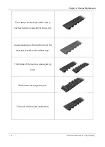
Page 31: ...he name of each part of the belt 2 2 1 Belt aging and wear reference standard Table 2 1 Belt aging and wear Belt aging and wear Status picture The tooth reinforcement of the belt disappears due to wea...

Page 32: ...022 The rubber on the back of the belt is cracked due to increased hardness etc Cracks develop in the tooth roots of the belt and extend to the rubber layer The flanks of the belt are damaged by wear...

Page 33: ...2 2 Transmission belt tension parameters Table 2 2 Belt Tension Parameters tooth shape width mm Tangent length mm Standard tension 10 n AH6K 3 shaft drive belt 3GT 15 200 74 10 AH6K J4 shaft primary t...

Page 34: ...dhere to the belt otherwise it will cause the belt to swell and significantly shorten the service life of the belt 3 Please avoid using or storing in extremely high or low temperature humid environmen...

Page 35: ...following table cannot be eliminated by mechanical ways please contact QKM for technical support Table 3 1 Handling of common exceptions Common Exception Possible Cause Handling Robot is in emergency...

Page 36: ...interface Replace with another network cable RS 232 communication port fails in communication Interface is damaged or plug is not inserted properly Replace the damaged interface Properly connect the p...

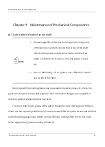
Page 37: ...ricating oil or grease can effectively extend service life of the robot Running out of lubricating grease may cause abnormal wear noise etc Check the grease on the spline screw shaft regularly If too...

Page 38: ...ft Non food industry AZ food machinery grease Micro vibration Stable nonhazardous Spline screw shaft Food industry Accessories special oil brush YMABALA KY1106 grease disposable protective gloves Figu...

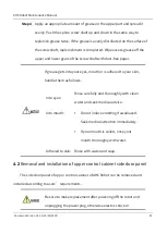
Page 39: ...screw shaft to the bottom as shown in Figure 4 2 Figure 4 2 Push down spline screw shaft Step 2 Wipe the old grease off the screw shaft with dust free paper and then apply an appropriate amount of gr...

Page 40: ...al Components 24 Document Version V1 1 2 19 09 2022 Figure 4 3 Apply lubricating grease Step 3 Press and hold the brake button and push the spline screw shaft up to the top as shown in Figure 4 4 Figu...

Page 41: ...your eyes mouth or is adhered to your skin handle them as follows Into eyes Rinse carefully and thoroughly with clean water and seek medical advice Into mouth Do not induce vomiting if swallowed Seek...

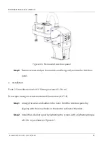
Page 42: ...nction may be caused Figure 4 5 Upper control cabinet side door panel Removal Tool 2 5 mm Allen wrench Screw type hexagon socket countersunk head screw M4 10 Step 1 Use 3 mm Allen wrench to remove scr...

Page 43: ...l Installation Tools 2 5 mm Allen wrench H3 50 torque wrench 1 5 N m Screw type hexagon socket countersunk head screw M4 10 Step 1 Arrange the wires and cables in the robot Hold the side door panel by...

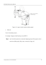
Page 44: ...on of side door panel When installing the side door panel do not clasp the cables or forcibly bend them to press in 4 3 Removal and installation of upper control cabinet interface panel Users can remo...

Page 45: ...Figure 4 8 Upper control cabinet interface panel Removal Tool 2 5 mm Allen wrench Screw type hexagon socket head cap screw M3 6 Step 1 Use 3 mm Allen wrench to remove the fastening screws from upper c...

Page 46: ...tallation Tools 2 5 mm Allen wrench H2 5 50 torque wrench 1 5 N m Screw type hexagon socket countersunk head screw M3 6 Step 1 Hold the upper control cabinet interface panel by aligning with the screw...

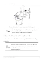
Page 47: ...interface panel do not clasp the cables or forcibly bend them to press in 4 4 Removal and installation of base interface panel Users can remove and install the base interface panel of AH6 Robot accord...

Page 48: ...V1 1 2 19 09 2022 Figure 4 11 Base interface panel Removal Tool 2 mm Allen wrench Screw type hexagon socket countersunk head screw M3 8 Step 1 Use 2 5 mm Allen wrench to remove the fastening screws f...

Page 49: ...ntrol cabinet and disconnect the connectors ground terminal etc of the upper control cabinet from the components in the base Step 3 Gently pull out the base interface panel and pay attention to preven...

Page 50: ...e hexagon socket countersunk head screw M3 8 Step 1 Arrange wires and cables in the base and connect the disconnected connectors and ground terminal on the controller in the upper control cabinet Step...

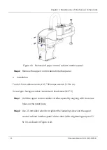
Page 51: ...clasp the cables or forcibly bend them to press in 4 5 Removal and installation of the second mechanical arm shell Users can remove and install the second mechanical arm shell of AH6 Robot according t...

Page 52: ...t button head screw M4 6 Step 1 When the robot is powered on while no servo wear disposable protective gloves press and hold the brake button on the second mechanical arm of the robot and push the spl...

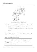
Page 53: ...econd mechanical arm shell Step 3 Remove the screws and put them aside and then gently pull the shell towards the bellows Step 4 Disconnect the connector of the system indicator from the robot interfa...

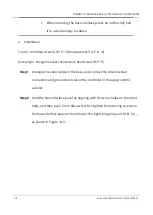
Page 54: ...wrench 1 5 N m Screw type hexagon socket button head screw M4 6 Step 1 Arrange wires and cables in the robot connect the system indicator to the interface put the shell into the slot and align with th...

Page 55: ...nance Manual Document Version V1 1 2 19 09 2022 39 Figure 4 17 Installation of the second mechanical arm shell When installing the second mechanical arm shell do not clasp the cables or forcibly bend...

Page 56: ...mal action of the robot which is very dangerous and may also cause electric shock or malfunction Do not allow foreign objects to enter the robot If the power is turned on when a foreign object enters...

Page 57: ...of the encoder battery is shown in Figure 5 1 In the case of continuous operation of the robot replace the battery every 1 5 years in the case of non continuous operation replace the battery once a ye...

Page 58: ...ep 1 Refer to Section 4 2 to remove the side door panel from the control cabinet of the robot Step 2 Remove screws from the part fixing the encoder battery as shown in Figure 5 2 and slowly pull out t...

Page 59: ...e controller communication module The robot will lose the zero point when the power supply for the encoder is interrupted To avoid this be sure to remove the old encoder battery after a new encoder ba...

Page 60: ...the side door panel of the upper control cabinet needs to be removed The position of the controller is shown in Figure 5 3 Back up data before replacing the controller After replacement copy the conf...

Page 61: ...p 1 Refer to Section 4 2 to remove the side door panel from the upper control cabinet of the robot Step 2 Unplug all the cables connected to the old controller Step 3 Loosen the screws on the control...

Page 62: ...emoval of fastening screws from controller bottom Step 4 Use 2 5 mm Allen wrench to remove the fastening screws from the bottom of the controller as shown in Figure 5 5 Step 5 Remove the old controlle...

Page 63: ...llation users shall check whether the interfaces match the line labels to avoid damage to the controller due to wrong connection Line labels corresponding to each interface are shown in the figure bel...

Page 64: ...CBA is shown in Figure 5 6 Figure 5 6 IO free distribution PCBA in the base Tools and accessories 2 5 mm Allen wrench static protective diagonal pliers cable tie gloves special assembly and disassembl...

Page 65: ...n the fastening screws on the IO free distribution PCBA and remove them The position of the screws is shown in Figure 5 7 Figure 5 7 Removal of IO free distribution PCBA Step 4 Use the special tool to...

Page 66: ...O free distribution PCBA on the base interface panel and tighten the screws Connect all cables to the new IO free distribution PCBA At the time of installation users shall check whether the interfaces...

Page 67: ...tection PCBA Surge protection PCBA is located in the base of the robot To replace it the base panel of the robot needs to be pulled out The position of surge protection PCBA is shown in Figure 5 9 Too...

Page 68: ...fer to Section 4 4 to remove the screws from the base interface panel of the robot and gently pull out the base interface panel Step 2 Unplug all cables connected to the surge protection PCBA Step 3 U...

Page 69: ...ghten the screws and then connect all cables to the new surge protection PCBA At the time of installation users shall check whether the interfaces match the line labels to avoid damage to the controll...

Page 70: ...in Figure 5 11 Tools and accessories 3 mm Allen wrench cable tie diagonal pliers filter static protective gloves Screw type hexagon socket head cap screw M4 8 Figure 5 11 Filter Step 1 Refer to Secti...

Page 71: ...ew filter on the part in the base and tighten the screws and then connect all cables to the new filter At the time of installation users shall check whether the interfaces match the line labels to avo...

Page 72: ...robot To replace it the base interface panel of the robot needs to be pulled out The position of the QBUS module is shown in Figure 5 13 Tools and accessories 3 mm Allen wrench cable tie diagonal plie...

Page 73: ...re 5 14 Figure 5 14 Removal of fastening screws from QBUS module Step 4 Install a new QBUS module on the part in the base and tighten the screws and then connect all cables to the new QBUS module At t...

Page 74: ...09 2022 Step 5 Refer to Section 4 4 to reinstall the base interface panel on the robot 5 7 Replacement and maintenance of QBUS fuse There are two QBUS fuses on the QBUS module as shown in Figure 5 15...

Page 75: ...ep 3 After installing a new fuse tighten the cover and restore the robot after replacement with reference to Section 4 4 5 8 Replacement and maintenance of 24V switching power supply 24V switching pow...

Page 76: ...ntly pull out the base interface panel Step 2 Unplug the 24V power plug and 220V power plug from the switching power supply The line labels of the 24V power plug include 24V 1 G24 24V 3 and G24 3 The...

Page 77: ...V power plug to the new switching power supply Step 5 Refer to Section 4 4 to reinstall the base panel on the robot 5 9 Replacement and maintenance of switching power supply fan assembly The switching...

Page 78: ...Find the switching power supply fan assembly Use the Allen wrench to turn counterclockwise to loosen the fastening screws on the motor fan Step 3 Gently unplug the connector of the switching power su...

Page 79: ...of the robot To replace it the second mechanical arm shell of the robot needs to be removed The brake PCBA in the second mechanical arm is shown in Figure 5 19 Tools and accessories cross screwdriver...

Page 80: ...n the brake PCBA in the second mechanical arm and remove them as shown in Figure 5 20 Figure 5 20 Removal of brake PCBA from the second mechanical arm Step 4 Install a new brake PCBA in the original p...

Page 81: ...AH6 Robot Maintenance Manual Document Version V1 1 2 19 09 2022 65 Step 5 Reinstall the second mechanical arm shell of the robot...

Page 82: ...u can contact our service department and provide as much information as possible Model and serial number of the robot nameplate on the back of the robot base Model and serial number of the control sys...

Page 83: ...AH6 Robot Maintenance Manual Document Version V1 1 2 19 09 2022 67...

Reviews: