background image


3


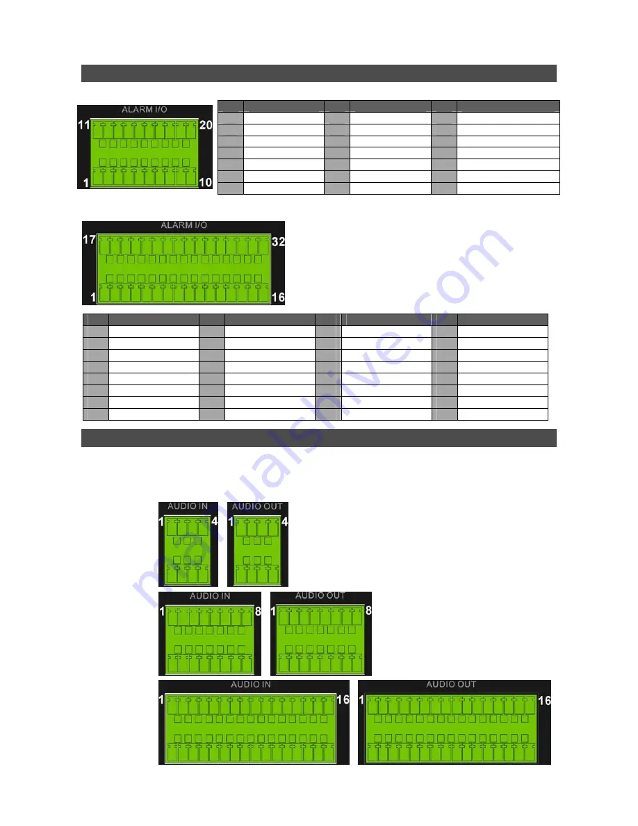
Pin Definition of Alarm I/O & RS-485   

4ch-Model / 8ch-Model: 

Pin  Definition 

Pin

Definition 

Pin  Definition 

RS485 D+ 

Normal Close B 

15 

Alarm In 5 (8ch model)

RS485 D


Common Node B

16 

Alarm In 6 (8ch model)

Ground 

10 

Normal Open B 

17 

Alarm In 7 (8ch model)

Normal Close A 

11 

Alarm In 1 

18 

Alarm In 8 (8ch model)

Common Node A

12 

Alarm In 2 

19 

N/A 

Normal Open A 

13 

Alarm In 3 

20 

N/A 


Ground 

14 

Alarm In 4 


16ch-Model: 


Pin  Definition 

Pin  Definition 

Pin

Definition 

Pin  Definition 

RS485 D+ 

Common Node B 

17 

Alarm In 1 

25 

Alarm In 9 

RS485 D


10 

Normal Open B 

18 

Alarm In 2 

26 

Alarm In 10 

Ground 

11 

Ground 

19 

Alarm In 3 

27 

Alarm In 11 

Normal Close A 

12 

Normal Close C 

20 

Alarm In 4 

28 

Alarm In 12 

Common Node A 

13 

Common Node C 

21 

Alarm In 5 

29 

Alarm In 13 

Normal Open A 

14 

Normal Open C 

22 

Alarm In 6 

30 

Alarm In 14 

Ground 

15 

Ground 

23 

Alarm In 7 

31 

Alarm In 15 

Normal Close B 

16 

Ground 

24 

Alarm In 8 

32 

Alarm In 16 


Pin Definition of Audio In / Audio Out   

For terminal blocks of Audio In and Audio Out, shown as below pictures, pins on the upper row are 
Audio In / Audio Out connectors for all channels, in sequential order from left to right. All other pins 
on the bottom row are for ground connection. 

4ch-Model:


8ch-Model:


16ch-Model:


Summary of Contents for Professional H.264

Page 1: ...rsor to previous or next fields To change the value in the selected field press UP DOWN keys 3 Shuttle Jog This is used to control playback operations 4 COPY This key is used for marking time in ezBur...

Page 2: ...provides alarm I O and RS 485 ports that offer users the flexibility required to connect the unit to other devices 11 NAS Device The NAS connector allows users to connect to a Network Attached Storag...

Page 3: ...5 Alarm In 9 2 RS485 D 10 Normal Open B 18 Alarm In 2 26 Alarm In 10 3 Ground 11 Ground 19 Alarm In 3 27 Alarm In 11 4 Normal Close A 12 Normal Close C 20 Alarm In 4 28 Alarm In 12 5 Common Node A 13...

Page 4: ...e Date Time using the Time Sync function Select Date Time in System Setup menu to enter the Date Time menu Select Time Zone to enter the time zone To find out your local time zone please visit wwp gre...

Page 5: ...id network conflicts From OSD main menu select System Setup Network Setup set the LAN Select item to LAN or PPPoE according to your network application and enter LAN Setup For DHCP user set the DHCP t...

Page 6: ...Places View Network Connections Create New Connection Set up an advance connection Accept incoming connections to accept connection from the DVR Select a modem then choose Do not allow virtual privat...

Page 7: ...to End Time and press ENTER will start playing recorded video from the specified End Time Use Direction keys to move the cursor for setting the Start Time adjusting the date and time values by UP DOWN...

Page 8: ...k video and return to live mode Using Remote Software Setup Requirements Make sure the PC is connected to the Internet Obtain IP address of your Professional H 264 DVR To check the DVR s IP address pr...

Page 9: ...e Login Screen is displayed Enter username and password The default username and password are admin 1234 The following picture shows the display window of the DVRRemote Refer to the table below for br...

Page 10: ...en and the file selection screen is displayed Select the drv video file to playback and click OK Click OK to start the playback or click Cancel to abort View the video playback using the Playback cont...

Reviews: