41057610TH Rev. 1
41 /
(2)
Do not try disassembly as long as the printer is operating normally.
(3)
Do not remove unnecessary parts: try to keep disassembly to a minimum.
(4)
Use specified service tools.
(5)
When disassembling, follow the determined sequence. Otherwise, parts may be damaged.
(6)
Since screws, collars and other small parts are likely to be lost, they should temporarily be
attached to the orginal positions.
(7)
When handling ICs such as microprocessors, ROM and RAM, and circuit boards, do not wear
gloves that are likely to generate static electricity.
(8)
Do not place printed circuit boards directly on the equipment or floor.
3.
PARTS REPLACEMENT
The section explains the procedures for replacement of parts, assemblies, and units in the field.
Only the removal procedures are explained here. Reverse the procedure for the installation.
3.1
Precautions for Parts Replacement
(1)
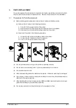
Before starting parts replacement, remove the AC cable and interface cable.
(a) Remove the AC cable in the following procedure:
i)
Turn off ("o") the power switch of the printer
ii)
Disconnect the AC inlet plug of the AC cable from the AC receptacle.
iii) Disconnect the AC cable and interface cable from the printer.
(b) Reconnect the printer in the following procedure.
i)
Connect the AC cable and interface cable to the printer.
ii)
Connect the AC inlet plug to the AC receptacle.
iii) Turn on ("l") the power switch of the printer.
Disconnect
Connect
Summary of Contents for OKICOLOR 8
Page 2: ...OKICOLOR 8 Color LED Page Printer Maintenance Manual 1999 7 14 Rev 1...
Page 12: ...41057610TH Rev 1 11 This page intentionally left blank...
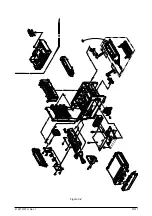
Page 44: ...41057610TH Rev 1 43 Figure 3 1 3 2 Parts Layout...
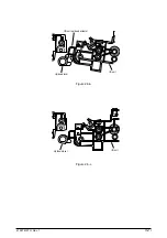
Page 45: ...41057610TH Rev 1 44 Figure 3 2...
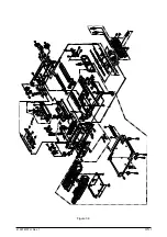
Page 46: ...41057610TH Rev 1 45 Figure 3 3...
Page 47: ...41057610TH Rev 1 46 Figure 3 4...
Page 105: ...41057610TH Rev 1 104 olor check pattern...
Page 156: ...41057610TH Rev 1 155 Fig 8 2 2 1 O 3 N C 0 9 Q 6 M J 8 7 8 S H E 7 K G 4 P D R L B A F T 5...
Page 166: ...41057610TH Rev 1 165 Fig 8 6 H B E F 2 J 4 4 I 3 3 6 9 8 7 G C D A 0 5 1 5...
Page 168: ...41057610TH Rev 1 167 Fig 8 7 1 2 5 6 3 4...
Page 170: ...41057610TH Rev 1 169 Fig 8 8 7 7 5 A 5 6 6 3 3 4 4 0 9 1 8 2...
Page 172: ...41057610TH Rev 1 171 Fig 8 9 7 6 6 5 5 4 1 8 8 2 3 4 3 7...
Page 196: ...41057610TH Rev 1 195 SEN1 CN22 CN23 CN24 5 2 PCB Layout AOLT PCB...
Page 197: ...41057610TH Rev 1 196 6 PARTS LIST 4 D 9 3 B 6 C A E F 2 J I L 0 1 K G G G 5 7 H 9 8...

