41057610TH Rev. 1
63 /
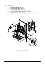
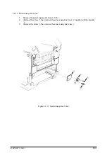
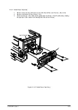
3.3.16 Power Supply Unit, Holder Inlet, Sheet Insulation
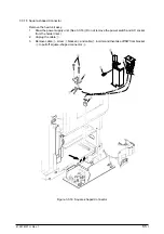
1.
Remove the motor-fan (80-25). (See 3.3.2)
2.
Remove the frame side (L), the cover assy side (R) and the cover rear (L). (See 3.3.8)
3.
Unplug the cable
1
.
4.
Remove the holder inlet
3
by unscrewing 2 screws
2
, then remove the power switch
4
and
unplug the AC socket
5
.
5.
Draw the power supply unit
7
by unscrewing 3 screws
6
, then unplug the cable
8
.
1
5
8
7
4
3
2
6
Figure 3.3.16 Power Supply Unit, Holder Inlet, Sheet Insulation
Summary of Contents for OKICOLOR 8
Page 2: ...OKICOLOR 8 Color LED Page Printer Maintenance Manual 1999 7 14 Rev 1...
Page 12: ...41057610TH Rev 1 11 This page intentionally left blank...
Page 44: ...41057610TH Rev 1 43 Figure 3 1 3 2 Parts Layout...
Page 45: ...41057610TH Rev 1 44 Figure 3 2...
Page 46: ...41057610TH Rev 1 45 Figure 3 3...
Page 47: ...41057610TH Rev 1 46 Figure 3 4...
Page 105: ...41057610TH Rev 1 104 olor check pattern...
Page 156: ...41057610TH Rev 1 155 Fig 8 2 2 1 O 3 N C 0 9 Q 6 M J 8 7 8 S H E 7 K G 4 P D R L B A F T 5...
Page 166: ...41057610TH Rev 1 165 Fig 8 6 H B E F 2 J 4 4 I 3 3 6 9 8 7 G C D A 0 5 1 5...
Page 168: ...41057610TH Rev 1 167 Fig 8 7 1 2 5 6 3 4...
Page 170: ...41057610TH Rev 1 169 Fig 8 8 7 7 5 A 5 6 6 3 3 4 4 0 9 1 8 2...
Page 172: ...41057610TH Rev 1 171 Fig 8 9 7 6 6 5 5 4 1 8 8 2 3 4 3 7...
Page 196: ...41057610TH Rev 1 195 SEN1 CN22 CN23 CN24 5 2 PCB Layout AOLT PCB...
Page 197: ...41057610TH Rev 1 196 6 PARTS LIST 4 D 9 3 B 6 C A E F 2 J I L 0 1 K G G G 5 7 H 9 8...

