41057610TH Rev. 1
55 /
3.3.8
Cover
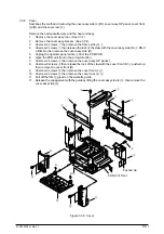
Describes the method of removing the cover assy side (L)/(R), cover assy OP panel, cover front
(L)/(R) and the cover rear (L).
Remove the belt cassette assy and the heat unit assy.
1.
Remove the cover assy rear. (See 3.3.1)
2.
Remove the cover assy stacker. (See 3.3.4)
3.
Unscrew 2 screws
1
then remove the frame side (L)
2
.
4.
Unscrew 2 screws
3
then release the lock of the claw with the cover assy side (R)
4
lifted
a little bit, then remove the cover assy side (R).
5.
Unplug the operator panel cable
5
from the PCM PCB.
6.
Open the FDR unit front in the arrow direction.
7.
Unscrew 2 screws
6
then remove the cover assy OP panel
7
.
8.
Unscrew 2 screws
8
then release the lock of the claw with the cover front (R)
9
pushed up
then remove the cover front (R).
9.
Unscrew 2 screws
0
then remove the cover front (L)
A
.
10. Unscrew 2 screws
B
then remove the cover rear (L)
C
.
11. Pull off the film
E
glued on the cassette guide.
11. Release the engagement with the guide by lifting the cover assy side (L)
D
, then remove the
cover assy side (L).
8
Pushed Up
B
4
3
7
5
1
6
2
A
D
0
E
C
FDR Unit Front
A
A
9
Figure 3.3.8 Cover
Summary of Contents for OKICOLOR 8
Page 2: ...OKICOLOR 8 Color LED Page Printer Maintenance Manual 1999 7 14 Rev 1...
Page 12: ...41057610TH Rev 1 11 This page intentionally left blank...
Page 44: ...41057610TH Rev 1 43 Figure 3 1 3 2 Parts Layout...
Page 45: ...41057610TH Rev 1 44 Figure 3 2...
Page 46: ...41057610TH Rev 1 45 Figure 3 3...
Page 47: ...41057610TH Rev 1 46 Figure 3 4...
Page 105: ...41057610TH Rev 1 104 olor check pattern...
Page 156: ...41057610TH Rev 1 155 Fig 8 2 2 1 O 3 N C 0 9 Q 6 M J 8 7 8 S H E 7 K G 4 P D R L B A F T 5...
Page 166: ...41057610TH Rev 1 165 Fig 8 6 H B E F 2 J 4 4 I 3 3 6 9 8 7 G C D A 0 5 1 5...
Page 168: ...41057610TH Rev 1 167 Fig 8 7 1 2 5 6 3 4...
Page 170: ...41057610TH Rev 1 169 Fig 8 8 7 7 5 A 5 6 6 3 3 4 4 0 9 1 8 2...
Page 172: ...41057610TH Rev 1 171 Fig 8 9 7 6 6 5 5 4 1 8 8 2 3 4 3 7...
Page 196: ...41057610TH Rev 1 195 SEN1 CN22 CN23 CN24 5 2 PCB Layout AOLT PCB...
Page 197: ...41057610TH Rev 1 196 6 PARTS LIST 4 D 9 3 B 6 C A E F 2 J I L 0 1 K G G G 5 7 H 9 8...

