41057610TH Rev. 1
135 /
4
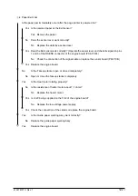
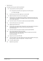
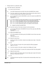
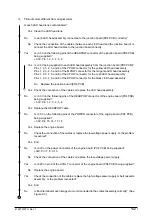
Black stripe or lines in the vertical direction
•
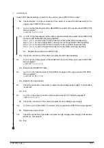
Is each LED head assembly connected to the junction board (PD6 PCB) correctly?
No
Connect the LED head assembly to the junction board correctly.
▼
•
Yes
Check the connection of the cables or replace the LED head assembly. Is the problem
recovered?
Yes End
▼
•
No
Check the connection of the cables or replace the junction board (PD6 PCB). Recovered?
Yes End
▼
•
No
Is engine board (PX4 PCB) connected to the junction board (PD6 PCB) correctly?
No
Connect the engine board to the junction board correctly.
▼
•
Yes
Check the connection of the cables or replace the engine board (PX4 PCB). Is the problem
recovered?
Yes End
▼
•
No
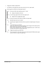
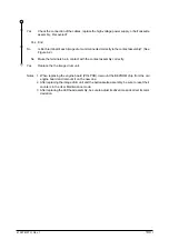
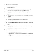
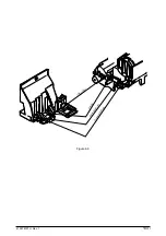
Is Each terminal of each image drum unit connected to the contact assembly correctly? (See
Figure 6.2.)
No
Make the terminals be in contact with the contact assembly correctly.
▼
•
Yes
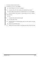
Replace the the image drum unit.
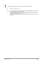
Notes: 1. When replacing the engine board (PX4 PCB), demount the EEPROM chip from the old
engine board and remount it on the new one.
2. After replacing the image drum unit, be sure to reset its counter in the User Maintenance
mode.
3. After replacing the LED head assembly, be sure to adjust its drive time and correct its color
deviation.
Summary of Contents for OKICOLOR 8
Page 2: ...OKICOLOR 8 Color LED Page Printer Maintenance Manual 1999 7 14 Rev 1...
Page 12: ...41057610TH Rev 1 11 This page intentionally left blank...
Page 44: ...41057610TH Rev 1 43 Figure 3 1 3 2 Parts Layout...
Page 45: ...41057610TH Rev 1 44 Figure 3 2...
Page 46: ...41057610TH Rev 1 45 Figure 3 3...
Page 47: ...41057610TH Rev 1 46 Figure 3 4...
Page 105: ...41057610TH Rev 1 104 olor check pattern...
Page 156: ...41057610TH Rev 1 155 Fig 8 2 2 1 O 3 N C 0 9 Q 6 M J 8 7 8 S H E 7 K G 4 P D R L B A F T 5...
Page 166: ...41057610TH Rev 1 165 Fig 8 6 H B E F 2 J 4 4 I 3 3 6 9 8 7 G C D A 0 5 1 5...
Page 168: ...41057610TH Rev 1 167 Fig 8 7 1 2 5 6 3 4...
Page 170: ...41057610TH Rev 1 169 Fig 8 8 7 7 5 A 5 6 6 3 3 4 4 0 9 1 8 2...
Page 172: ...41057610TH Rev 1 171 Fig 8 9 7 6 6 5 5 4 1 8 8 2 3 4 3 7...
Page 196: ...41057610TH Rev 1 195 SEN1 CN22 CN23 CN24 5 2 PCB Layout AOLT PCB...
Page 197: ...41057610TH Rev 1 196 6 PARTS LIST 4 D 9 3 B 6 C A E F 2 J I L 0 1 K G G G 5 7 H 9 8...


