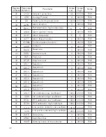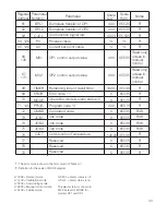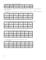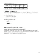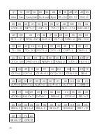
7-3 Parameter Table
Parameter
Scale
Low
Scale
High
Notes
0
1
2
3
4
5
6
7
8
9
10
11
12
13
14
15
16
17
18
19
20
21
22
23
24
SP1
SP2
SP3
LOCK
INPT
UNIT
DP
INLO
INHI
SP1L
SP1H
SHIF
FILT
DISP
PB
TI
TD
OUT1
O1TY
O1FT
O1HY
CYC1
OFST
RAMP
RR
Set point 1
Set point 2
Set point 3
Lock code
Input sensor selection
Measuring unit
Decimal point position
Low scale value for linear input
High scale value for linear input
Low limit of SP1
High limit of SP1
PV shift value
Filter time constant
Display form ( for C21 )
P ( proportional ) band
Integral time
Derivative time
Output 1 function
Output 1 signal type
Output 1 failure transfer
Output 1 ON-OFF hysteresis
Output 1 cycle time
Offset value for P control
Ramp function
Ramp rate
*4
*7
*6
0
0
0
0
*4
*4
*4
*4
*4
0
0
*5
0
0.0
0
0
-1999.9
*5
0.0
0.0
0
0
0
*5
*5
*4
*7
*6
65535
65535
65535
65535
*4
*4
*4
*4
*4
65535
65535
*5
65535
6553.5
65535
65535
4553.6
*5
6553.5
6553.5
65535
65535
65535
*5
4553.6
R/W
R/W
R/W
R/W
R/W
R/W
R/W
R/W
R/W
R/W
R/W
R/W
R/W
R/W
R/W
R/W
R/W
R/W
R/W
R/W
R/W
R/W
R/W
R/W
R/W
R/W
R/W
R/W
R/W
R/W
Register
Address
Parameter
Notation
*5
25
26
27
28
29
OUT2
O2TY
O2FT
O2HY
Output 2 function
Output 2 signal type
Output 2 failure transfer
Output 2 ON-OFF hysteresis
-1999.9
RELO
Retransmission low scale value
*4
*4
41

