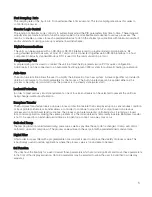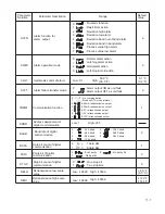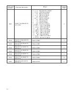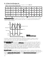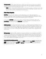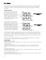
: Characters Displayed by a Symbol
Table 1.1 Character Legend
A
E
I
N
S
X
B
F
J
O
T
Y
C
G
K
P
U
Z
c
H
L
Q
V
?
D
h
M
R
W
=
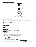
Figure 1.3 Front Panel Description
The ETR-9100 goes through an initial Power up self test during
which it displays the Program code and version of the controller.
The left diagram shows program version 6.24 for an ETR-9100.
Displays the program code of the product for 2.5 seconds.
Figure 1.4
Display at Power-up
8
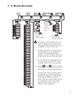
Upper Display, to display process value,
menu symbol and error code etc.
Lower Display,
to display set point value,
parameter value or
control output value etc.
4 Buttons for ease of
control setup and
set point adjustment.
Output 1
Indicator
Output 2
Indicator
Alarm
Indicator
Process Unit Indicator
Manual
Mode
Indicator
Auto-tuning
Indicator
OP1 OP2 ALM
C
F
MAN
AT
ETR-9100
R
OP1 OP2 ALM
C
F
MAN
AT
ETR-9100
R

