- 2 -
2
BASIC PARAMETERS
ZÁKLADNÍ PARAMETRY
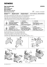
min. 0 mm
MCR-MB
16 15 18
A1 A2 TL
1
.1
.2
.3
.4
.5 .6
.7
.8
.9
t
t
fc
1s
10
1m
10
1h
10
100
OFF
F1
F2
F3
F4 F5
F6
F7
F8
test
U
R
MCR-MB
16 15 18
A1 A2 TL
1
.1
.2
.3
.4
.5 .6
.7
.8
.9
t
t
fc
1s
10
1m
10
1h
10
100
OFF
F1
F2
F3
F4 F5
F6
F7
F8
test
U
R
MCR-MB
16 15 18
A1 A2 TL
1
.1
.2
.3
.4
.5 .6
.7
.8
.9
t
t
fc
1s
10
1m
10
1h
10
100
OFF
F1
F2
F3
F4 F5
F6
F7
F8
test
U
R
MCR-MB
16 15 18
A1 A2 TL
1
.1
.2
.3
.4
.5 .6
.7
.8
.9
t
t
fc
1s
10
1m
10
1h
10
100
OFF
F1
F2
F3
F4 F5
F6
F7
F8
test
U
R
fc
OFF
F10
F11
F12
F13 F14
F15
F16
F17
F18
fc
OFF
F10
F11
F12
F13 F14
F15
F16
F17
F18
fc
OFF
F10
F11
F12
F13 F14
F15
F16
F17
F18
fc
OFF
F10
F11
F12
F13 F14
F15
F16
F17
F18
min. 9 mm
MCR-MB
26 25 28
16 15 18
36 35 38
A1 A2 TL
1
.1
.2
.3
.4
.5 .6
.7
.8
.9
t
t
fc
1s
10
1m
10
1h
10
100
OFF
F1
F2
F3
F4 F5
F6
F7
F8
test
U
R
MCR-MB
26 25 28
16 15 18
36 35 38
A1 A2 TL
1
.1
.2
.3
.4
.5 .6
.7
.8
.9
t
t
fc
1s
10
1m
10
1h
10
100
OFF
F1
F2
F3
F4 F5
F6
F7
F8
test
U
R
MCR-MB
26 25 28
16 15 18
36 35 38
A1 A2 TL
1
.1
.2
.3
.4
.5 .6
.7
.8
.9
t
t
fc
1s
10
1m
10
1h
10
100
OFF
F1
F2
F3
F4 F5
F6
F7
F8
test
U
R
MCR-MB
26 25 28
16 15 18
36 35 38
A1 A2 TL
1
.1
.2
.3
.4
.5 .6
.7
.8
.9
t
t
fc
1s
10
1m
10
1h
10
100
OFF
F1
F2
F3
F4 F5
F6
F7
F8
test
U
R
fc
OFF
F10
F11
F12
F13 F14
F15
F16
F17
F18
fc
OFF
F10
F11
F12
F13 F14
F15
F16
F17
F18
fc
OFF
F10
F11
F12
F13 F14
F15
F16
F17
F18
fc
OFF
F10
F11
F12
F13 F14
F15
F16
F17
F18
1
3
4
5
6
7
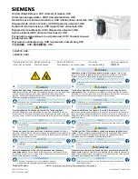
Description
Popis
Output contacts
Výstupní kontakty
Output indication, yellow LED
Indikace výstupu, žlutá LED
Supply voltage
indication
,
green
LED
Indikace napájecího napětí, zelená LED
Setting of time delay t
Nastavení časové prodlevy t
Function selection
Výběr funkce
Supply voltage
Napájecí napětí
2
Control
Ovládání
MCR-MB-001-UNI
MCR-MB-003-UNI
MCR-MB-003-UNI
Wiring diagram
Schéma zapojení
A1
A2
T
16 18
15
26 28
25
36 38
35
TL
MCR-MB-003-UNI
A1
A2
T
16 18
15
MCR-MB-001-UNI
TL
MCR-MB-003-UNI
2
3
7
7
5
6
4
3
7
1
26 25 28
16 15 18
36 35 38
A1 A2 TL
MCR-MB
t
t
fc
fc
OFF
F1
F2
F3
F4 F5
F6
F7
F8
test
OFF
F10
F11
F12
F13 F14
F15
F16
F17
F18
U
R
1s
10
1m
10
1h
10
100
1
.1
.2
.3
.4
.5 .6
.7
.8
.9
MCR-MB-003-UNI
-
20
°C
…
+
55
°C
-
40
°C
…
+
70
°C
7 mm
2
max. 2x 1,5 mm
2
max. 1x 2,5
mm
8 A / 250 V ~ µ cos = 1
φ
U /P
c
2
max. 2x 1,5 mm
2
max. 1x 2,5
mm
MCR-MB-001-UNI
AC 12
230 V / 0,7
2,1 VA
DC 12
220 V / 0,9
1,2 W
AC 24
230 V / 0,7
2,1 VA
DC 24
220 V / 0,9
1,2 W
+
-
+
-
P
2 000 VA
192 W
200 W
200 W
2
2
2
AC-1
DC-1
AC-3
AC-5b
Z00
994074b
T
T1
T2
Re ON
DCL
=
• 100 [%]
T1
T
Re ON
T1 ≤ 1 hod
I = 8 A
n
Doba sepnutí
Make time
Teplota okolí
Ambient temperature
t ≤ 25 °C
o
DCL
≤ 25
%
Střída
Duty cycle
Normal activity
Normální činnost
Other cases
Ostatní případy