NTI VEEMUX SM-nXm-C5AV-1000 Installation And Operation Manual Download Page 46

NTI VEEMUX AUDIO VIDEO MATRIX SWITCH VIA CAT5 


41


Scanning Sequences 


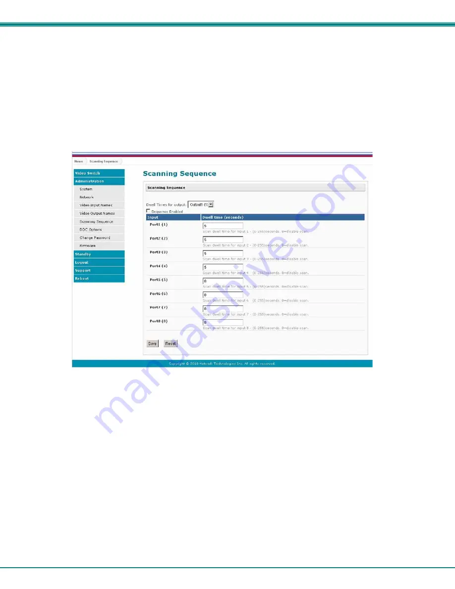
From the Administration menu, the Scanning Sequence page can be displayed.   The Scanning Sequence page displays the 
configuration of an automatic switching sequence from input (video source) to input for each output (monitor).     


The page displays: 

ƒ


output number being configured  

ƒ


the Scanning Sequence function status for that output  

ƒ


the length of time in seconds (dwell time) that each input will be viewed when connected- the dwell 
time value ranges from 0-32000 seconds 


                                                         Figure 19- Scanning Sequence page 


The output selection at the top of the page can be changed to any output to display the Scan Sequence Input dwell time values for 
that output.     


The inputs and the amount of time that each will be viewed (0-32000 seconds) can be set to cycle sequentially for each connected 
output.   If an input is set to 0 seconds, that input will not be viewed and will be skipped from the scanning sequence.    To include 
an input in the sequence, enter a dwell time period from 1-32000 seconds, and press “

Save”

.  


If you make changes and change your mind and want to return the values back to what they were before changing them,   press 

Reset

”.    This must be done before pressing the “

Save

” button, or changes will not be able to be reversed.  


To enable the scanning sequence for the output shown, place a checkmark in the “Sequence Enabled” block.    


Tip: To quickly enable the scan sequence for multiple outputs, use the “Sequence Enable” blocks found on the Switch 
Page (page 18).  


Note: If only one input has a dwell time value entered, then the output connection to that input will not end when the 
Scanning Sequence is enabled.       

Summary of Contents for VEEMUX SM-nXm-C5AV-1000

Page 1: ...MAN148 Rev Date 03 12 2014 SM nXm C5AV 1000 Audio Video Matrix Switch via CAT5 Installation and Operation Manual VEEMUX Series...

Page 2: ...nsmitted in any form or by any means electronic mechanical photocopying recording or otherwise without the prior written consent of Network Technologies Inc 1275 Danner Drive Aurora Ohio 44202 CHANGES...

Page 3: ...sing the USB Console Port 22 RS232 Control 23 Remote Connection 23 Baud Rate 23 Unit Address and Loop Back 23 Command Protocol 25 Autostatus 26 Matrix Switcher s Control Program For Windows 9X NT 2000...

Page 4: ...out 46 Support 47 Reboot 47 Device Discovery Tool 48 How to Use the Device Discovery Tool 48 Infrared Remote Control 49 Materials 49 Buttons 50 Operation 51 Changing Ports 51 Channel Surfing 51 Jump T...

Page 5: ...rt in Matrix Switcher s Control Program 22 Figure 11 RS232 connection with Matrix Y 1 cable 24 Figure 12 Pinout of Matrix Y 1 cable 24 Figure 13 Web interface Login page 34 Figure 14 Main menu and Vid...

Page 6: ...y connection change or can be forced via the front panel or web interface Equipped with Liquid Crystal Display LCD for front panel operation A digital VU meter shows the audio levels of the selected i...

Page 7: ...see http www networktechinc com cable pc html A SA xx MM stereo audio cable for each set of self powered speakers being locally connected to the switch see http www vpi us cable audio 3 5 html A CAT5...

Page 8: ...x16 model 9 None Power Switch For powering ON and OFF the VEEMUX 10 AC INPUT IEC Connector For attachment of the IEC power cord to power the VEEMUX 11 AUD OUT 3 5mm Stereo Jack For connection of audio...

Page 9: ...ns of strain relief for cables For models SM nX64 C5AV 1000 Your NTI Switch was designed for easy installation by one person with a minimum of tools and effort Follow the simple steps below to quickly...

Page 10: ...t the front of the rack in positions where the VEEMUX will be mounted three in each side Install four more cage nuts at the rear of the rack where the upper and lower flange holes will be located as s...

Page 11: ...mbly in the same fashion The end with the label Left Front mounts to the front rack support 5 Install two 10 32 x 3 4 pan head screws in the rear of each rail assembly as shown below Do not tighten at...

Page 12: ...nd slide the VEEMUX into the rack 8 Apply four more 10 32 x 3 4 pan head machine screws two for each through the holes in the front panel through the holes in the washer lowermost holes only into the...

Page 13: ...SWITCH VIA CAT5 8 10 Tighten the 4 screws securing the front panel to the rack 11 Tighten securely the four screws applied to the rear rail flanges in step 5 12 Make your cable connections according t...

Page 14: ...S 1000SP VGA Video two way audio RS232 1 VGA inputs only work with VGA outputs S Video inputs only work with S Video outputs and HDTV component video inputs only work with HDTV component video outputs...

Page 15: ...onnect Extended Sources and Devices 1 Connect CATx cables from XTENDEX transmitters to ports marked CATx IN Figure 2 Connect XTENDEX Transmitters 2 Connect CATx cables from XTENDEX receivers to ports...

Page 16: ...port 16 The same rule applies when larger models have additional rows of input ports 1 Make connections from any VGA video or stereo audio source directly to the connectors provided Figure 4 VGA Video...

Page 17: ...beled ETHERNET and the LAN see Fig 4 Figure 6 Connect the VEEMUX to the LAN Serial Connection If control via serial connection is going to be used serial control can be achieved using the USB Console...

Page 18: ...TRIX SWITCH VIA CAT5 13 To use the USB CONSOLE port connect a USB cable 1 meter cable supplied between the VEEMUX and your PC Then install the drivers as described on page 18 Figure 8 Serial Connectio...

Page 19: ...the switch When the unit is first powered up each monitor is automatically connected to the video source of its equal number i e monitor 1 to source 1 monitor 2 to source 2 monitor 3 to source 3 etc...

Page 20: ...ig 6 Load Config 7 VU Meter 8 LCD Contrast Use the Up and Down Arrow keys to scroll through this list Use the Enter Key to select a menu item Press the List button again to exit the menu If while in a...

Page 21: ...s found it uses the information found at the remote connected to port 1 4 The fourth option in the main menu is Standby If you select Standby the VEEMUX switch will immediately go into a power saver m...

Page 22: ...t for which the information is displayed is indicated on the LCD below the information Use the arrow buttons to scroll up or down to display the volume level for other audio sources LCD Contrast The b...

Page 23: ...s A driver file compatible with Windows XP 2000 Vista and 7 32 and 64 bit versions can be found on the CD that came with your VEEMUX Browse to the drive your Product Manual CD is in and locate and sel...

Page 24: ...dware Wizard search for the driver but direct it to the drive the Product Manual CD is in and the directory of either the 32 bit driver or the 64 bit driver D Once the driver is installed you will get...

Page 25: ...Press Close B Open the Device Manger and select the VEEMUX in the device list Right click and open Properties Select Update Driver Software Tip The Device Manager can be opened by right clicking on M...

Page 26: ...computer for the usbser sys file it needs Once it does you will get a window telling you Windows is finished Take note of the COM port number it assigned This one assigned COM3 E You will probably get...

Page 27: ...ou didn t take note of it during installation Figure 9 COM port assigned to VEEMUX Using the USB Console Port The virtual COM port will be used to enable serial control over the VEEMUX see RS232 contr...

Page 28: ...on to most CPUs see page 12 To daisy chain multiple units connect a Matrix Y 1 cable sold separately between the CPU and the first switch and between each switch as shown in Figure 11 Baud Rate The ba...

Page 29: ...Unit 2 9D Female 9D Male 9D Male Wiring Schematic of Matrix Y 1 cable NTI SWITCH CPU RS232 First Unit NTI SWITCH RS232 NTI SWITCH RS232 Second Unit Last Unit RS232 Serial Port Matrix Y 1 Matrix Y 1 M...

Page 30: ...ber of digits is minimum 1 and maximum 3 for each field Leading zeroes are accepted EM SW ip CR Set the Subnet mask ip is in xxx xxx xxx xxx format number of digits is minimum 1 and maximum 3 for each...

Page 31: ...ontrols NTI matrix switches through an RS232 interface The Matrix Switcher s Control Program is downloaded by clicking on the link Download Matrix Switcher s Control Program found on the web page that...

Page 32: ...tions from switch memory bank c Change All Units Baud Rate 9600 COM1 change RS 232 Baud rate of all switches the current baud rate and serial port are displayed in parentheses d Reset Unit send a rese...

Page 33: ...n parentheses 4 set read timeout 5 select the time period in seconds the SerTest will wait for an answer to a command the current time period is displayed in parentheses For any selection that require...

Page 34: ...mands Help CS nn mm CR Connect One input nn To output mm CA nn CR Connect All Outputs To Input nn RO mm CR nn CR Read Connection For Output Returns the number of the input nn connected to output mm CC...

Page 35: ...ort 01 MAXOUTPUTS IP Input Port 01 MAXINPUTS CR Carriage Return Hex 0xD Command Summary Command String Good Response Description RU CR ru IP OP CR Read unit size RO OP CR pc OP IP CR Read connection f...

Page 36: ...4 Byte 5 Byte 6 R 0x52 O 0x4F Space 0x20 Output 1st digit 0x30 0x32 Output 2nd digit 0x30 0x39 CR 0x0D Response Byte 1 Byte 2 Byte 3 Byte 4 Byte 5 Byte 6 Byte 7 Byte 8 Byte 9 p 0x70 c 0x63 Space 0x20...

Page 37: ...and this command must be entered to enable it When auto status mode is enabled a message will be sent whenever an input output connection changes from any source The format of this message is given in...

Page 38: ...0x30 0x32 Input 2nd digit 0x30 0x39 CR 0x0D Byte 1 Byte 2 Byte 3 Byte 4 Byte 5 Byte 6 Byte 7 Byte 8 Byte 9 p 0x70 c 0x63 Space 0x20 Output 1st digit 0x30 0x32 Output 2nd digit 0x30 0x39 0x3A Input 1st...

Page 39: ...nt IP address into the address bar of the web browser Address To open a SSL encrypted connection type Address You will be prompted to accept a certificate Accept the NTI certificate A Login Page will...

Page 40: ...connection method Scanning Sequences page 41 for each output can also be enabled Note Changes made using the keypad page 14 or by another user through the web interface will be updated automatically t...

Page 41: ...ion To blank the video to a specific output click the box to the right of Blank that corresponds with the desired output to place a checkmark in it The video going to that output will be disabled To e...

Page 42: ...word used to access the VEEMUX Firmware Update the firmware as new versions become available System Configuration On the System Configuration page under Administration fields are provided to assign a...

Page 43: ...Settings Mode Choose between Static IP assignment and DHCP IP Address If using Static IP assignment enter a valid IP address to use Subnet Mask Enter a valid subnet mask value Default Gateway Enter a...

Page 44: ...ive web connection will stay logged in The range is 0 3200 minutes 0 disables it Any change to the Website Timeout configuration takes effect immediately Press the Save button to save any changes made...

Page 45: ...output ports displayed on the Switch page Figure 18 Video Output Names page To change an Output Name enter the name of the port for the desired output port number and press Save If you make changes a...

Page 46: ...he amount of time that each will be viewed 0 32000 seconds can be set to cycle sequentially for each connected output If an input is set to 0 seconds that input will not be viewed and will be skipped...

Page 47: ...selections and establish a connection and starting point for the scanning sequence Blocks shown in yellow in the third image indicate connections made 3 Click on the Sequence Enable box for each outpu...

Page 48: ...til the Clear DDC data button is selected Mix The VEEMUX will poll all remote monitors for EDID information and compile a list looking for common information Once found the common EDID parameter will...

Page 49: ...strator to change the password used to access the VEEMUX This password is also used for the telnet interface Be sure to make note of the new password exactly as it is case sensitive The password must...

Page 50: ...computer 2 On the Update Firmware page in the Update File block browse to the firmware file 3 Press Upgrade Note If an update is attempted using the wrong firmware for the section an error message wil...

Page 51: ...menu the VEEMUX is placed in Standby Mode When in Standby Mode the VEEMUX is still operating as configured but cannot be manipulated further until standby is disabled Standby Mode can be disabled eit...

Page 52: ...Video Matrix Switch via CAT5 at NTI From there you can see what versions of firmware are available and determine if the version in your VEEMUX is current or in need of an upgrade page 45 Figure 25 Sup...

Page 53: ...d will be displayed Tip If your Windows program asks which program to open the NTIDiscover jar file with select the Java program Figure 27 Device Discovery Tool Click on the Detect NTI Devices button...

Page 54: ...tions and put the switch into Standby Features Ability to switch one input to all outputs Scroll through inputs for a single output by using the Input keys similar to changing channels Automatically s...

Page 55: ...nections and volume settings Up to 10 configuration can be recalled 0 9 SYS Pressed to select the desired NTI system to be controlled Only used when controlling multiple systems Must be followed by a...

Page 56: ...n becomes which output connection is being changed As a result it is required that an output be selected prior to using the IN buttons The output port can be selected in two ways by pressing the OUT b...

Page 57: ...input port has been selected the output port can be selected following the same format as Jump to Input Expiration of a five 5 second timeout will force the switch to forget the entered input port num...

Page 58: ...can be used to select the NTI switch to be controlled All switches will have the capability to allow the user to set the switch address 0 15 Each switch to be separately controlled must be set to a di...

Page 59: ...rts Audio Connectors 3 5mm jack Audio Signal Type Stereo unbalanced Audio Frequency response THD N S N Crosstalk 20Hz to 20kHz 1 0dB 0 01 1kHz 76 dB 70 dB 1kHz Audio Input Impedance Max input level 10...

Page 60: ...emote extender Distorted audio and or video Cable is run through electronically noisy environment Make sure you have good quality CATx cable Make sure the cable runs are as far away from any source of...

Page 61: ...t 3 Scanning Sequences 41 SerTest 27 source switch 11 standby mode 46 Telnet 12 Telnet Interface 29 Telnet Port 2005 30 USB COM port 18 username and password 34 Video Switch 35 web browsers 1 WARRANTY...

Reviews: