


— 2-17 —
2.7. Driver Unit Specifications
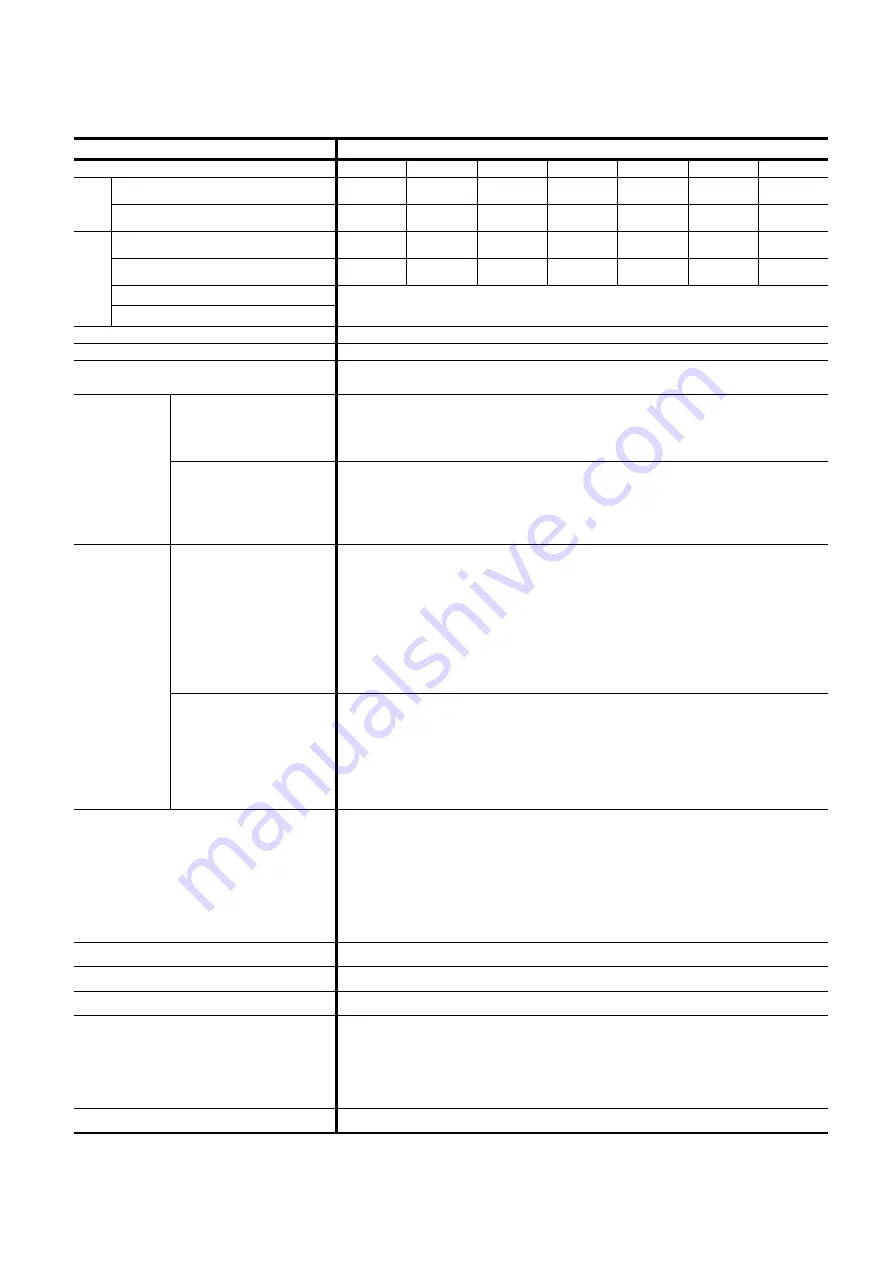
Table 2-8: Specifications of EDC Driver Unit (1)
Item Specification
Motor type
PS1006
PS1012
PS1018
PS3015
PS3030 PS3060
PS3090
Continuous output [Arms]
0.8 1.2 2.1 2.1 2.5 4.1 4.0
Outpu
t
curren
t
Maximum output [Arms]
2.4 3.5 5.8 6.6 8.2 14.9
14.9
Rated capacity [VA]
0.3 0.4 0.5 0.5 0.8 0.4 0.6
Max. capacity [VA]
1.0 1.5 2.0 2.3 2.9 5.0 5.5
Control power
Input
power Main power
Single phase 100 to 115 [VAC] / Single phase 200 to 230 [VAC]
50/60[Hz]Voltage Fluctuation: ±10[%] or less
Position sensor resolution [count/revolution]
2 621 440
Maximum velocity speed[s
-1
]
10 (Depends on the Motor type. Refer to “2.5. Motor Specifications.”)
Positioning operation mode
Program operation (256 program channels), Pulse train command, RS-232C
serial communication command, Jogging, Home Return
Pulse train command
Photo coupler input. Maximum frequency 1 MHz
Input format: CW/CCW, Pulse & direction or øA/øB
Resolution changer for free manipulation is available.
(1000 to 5 242 880 [count/revolution])
Input signal
Control input
Photo coupler (± common), 17 input ports. Input voltage: 24 VDC
Emergency stop, Alarm clear, Over travel limit + direction, Over travel limit –
direction, Servo ON, Program operation start, Stop, Internal program channel
switching 0 to 7, Jog, Jog direction, (Hold, Velocity override, Integration OFF,
Home Return start, and Home position limit)
*1
Position feedback
signal
Signal format: øA/øB/øZ line driver. Free resolution setting to øA/øB
is
available.
Resolution of øA/øB:
Shipping set: 20 480 [count/revolution] (Quadrupled: 81 920 )
Maximum: 1 310 720 [count/revolution] (Quadrupled: 5 342 880)
*Because the maximum frequency is 781 [kHz], the setting of the resolution
limits the maximum rotational speed. (Max. velocity = 781 [kHz]/
resolution of øA (øB)
Resolution of øZ: 80 [count/revolution]
Output
signal
Control output
Photo coupler (± common), 8 output ports.
Max. switching capacity: 24 VDC/50 [mA]
Driver Unit ready, Warning, Over travel limit det/- direction, Servo
state, Busy, In-position, Target proximity A (Target proximity B, Zone A•B•C,
Travel limit +/-, Normal, Position error under/over, Velocity under/over,
Torque command under/over, Thermal loading under/over, Home Return
complete, Home position defined)
*2
Alarm
Excess error, Program error, Automatic tuning error, Field bus warning,
Position command/Feedback error, Software thermal error, Home position
undefined, Main AC line under voltage, Travel limit over, RAM error, ROM
error, System error, Interface error, ADC error, Emergency stop, CPU error,
Field bass error, Position sensor error, Absolute position error, Motor cable
disconnected, Excess velocity, Resolver excitation amplifier alarm,
Commutation error, Overheat, Main AC line over voltage, Excess current,
Control AC line under voltage, Power module error
Monitors
Analog monitor ×2, (Free range and offset setting), RS~232C monitor
Communication
RS-232C serial communication (Asynchronous, 9600 bps)
Data backup
EEPROM (Overwriting and deleting of parameters are limited to 100 000 times.)
Others
•
Automatic tuning
•
Function set to Input/Output ports available
•
Temporal parameter setting by program is available
•
Individual acceleration/deceleration setting
•
Acceleration profiling
Field bus
CC-Link Ver.1.10 compatible (optional)
*1: Change of function assignment of the Input/Output ports will make these functions effective.
*2: These control outputs become effective when these function is assigned to the output port.
Summary of Contents for Megatorque PS Series
Page 52: ... 2 32 Blank Page ...
Page 72: ... 4 6 Blank Page ...
Page 122: ... 6 34 Blank Page ...
Page 160: ... 7 38 Blank Page ...
Page 340: ... 11 24 Blank Page ...
Page 368: ... A 24 Blank Page ...
Page 370: ......