background image

O

PTIONS

G-46 MDB

14

National Rejectors, Inc. GmbH, Buxtehude

With another programming station you can update the program of the new
G-40.4000/3 series. This programming station includes

the tester G-19.0641,

the programming adapter G-19.0646 and

a software available at NRI upon request with the following system
requirements:
– MS-DOS operating system from version 3.3
– working memory of at least 512 KB
– serial interface COM1/COM2.

Summary of Contents for G-46 MDB

Page 1: ...ational Rejectors Inc GmbH Zum Fruchthof 6 D 21614 Buxtehude Telefon 49 0 4161 729 0 Telefax 49 0 4161 729 115 e mail info nri de Internet www nri de CRANE 11 02 Schn vBi ds Edition 3 0 HB MDBG46 GB Coin changer G 46 MDB Manual ...

Page 2: ......

Page 3: ...ses Optional payout combinations by simply changing the tubes Longer tubes and an additional 4th tube offer an optimum change capacity Universal application in almost all machines simply by using a different connecting cable or interface module Fast service due to error diagnosis Individual combination with peripheral devices and adaptation to all market demands Splash proof electronics Monitored ...

Page 4: ......

Page 5: ...ng module G 55 0460 12 Palm handheld G 46 4 Setting Program 12 Palm handheld program PalmEMP1 13 Programming stations 13 4 Design and function of the G 46 15 Overview of the device 15 Sorting the coins 16 Payout set with interchangeable tubes 16 Measuring principle 16 Programmed coin channels 17 Inhibiting coin channels with DIL switches 18 Selecting memory block 0 and 1 with DIL switch 20 5 Trans...

Page 6: ...Ser 01 28 8 Programming functions 29 Structure of the PRO functions 29 Adding up credit which cannot be shown on the vending machine display Pro 0401 31 Release of inventory keys via the machine control Pro 0401 31 Pay out security stock 0401 32 Accept only tube coins when filling the tubes 0404 32 Not enable inventory keys via machine control 0404 33 Inhibiting individual coins Pro 15 33 Setting ...

Page 7: ... the tubes Ser 06 38 10 Remedying faults 39 Solving actual problems 39 Error display via the internal LED 40 Reading out error messages via the setting module 40 11 Cleaning the changer 43 12 Repairing and exchanging components 44 Exchanging tubes 44 Exchanging the payout set 47 Exchanging the interface module 48 13 Technical Data 50 CE Certification 51 ...

Page 8: ......

Page 9: ... not onlyhaveanadditionaltube butalsolengthenedtubes morecoinchannels and further functions The coin validator offers a reliable sensing system and rejection of false coins with the proved and well known coin validator G 40 4000 Due to the modular design you can individually combine your changer with accessories see chap 3 Options Configuration is carried out via a PC Palm handheld or via the sett...

Page 10: ...orientation within this manual and the operation of the device the following fonts and signs were used in the text Safety instructions which have to be complied with in order to protect operator and devices have been written in bold writing and a pictogram has been used Special notes which are meant to help the user use the coin validator have been written in italics and also been identified with ...

Page 11: ...lidator pcb is fitted with components which may be damaged beyond repair by electrostatic charges Please observe the handling instructions for components at risk due to static Select the correct voltage for each changer see label Never remove the coin validator s connecting cable from the changer when it is live Remove the vending machine s plug from the socket before installing cleaning or removi...

Page 12: ...odule and the two Palm handheld programs G 46 4 Setting Program and PalmEMP1 Setting module G 55 0460 The setting module enables you to read out error messages check or change adjustments PRO mode carry out service functions SER mode Chapter 6 Connecting and operating the setting module will give you further information about its function Palm handheld G 46 4 Setting Program The Palm handheld soft...

Page 13: ...of the changer to your machine The WinEMP programming station includes the tester G 19 0641 a test stand G 19 0643 for the complete changer or G 19 0584 for the coin validator the software WinEMP with the following system requirements operating system Windows 95b 95c 98 NT 2000 XP not CE working memory of at least 32 MB CD ROM drive graphic resolution 800 x 600 dpi min High Color serial interface ...

Page 14: ...program of the new G 40 4000 3 series This programming station includes the tester G 19 0641 the programming adapter G 19 0646 and a software available at NRI upon request with the following system requirements MS DOS operating system from version 3 3 working memory of at least 512 KB serial interface COM1 COM2 ...

Page 15: ...c GmbH Buxtehude 4 Design and function of the G 46 Overview of the device Coin validator Internal keyboard Interface setting module Label Tube Payout module Interface machine printer etc Interface PC Dummy plug Return lever Coin insert funnel Fig 1 Design of the G 46 ...

Page 16: ...tes a full tube the coin falls into the cash box Payout set with interchangeable tubes The payout set consists of the payout module and 4 coin tubes In order to guarantee a reliable payout of coins with different diameters you can choose the suitable tubes from various coin tubes with different diameters Measuring principle Coins inserted into the coin validator pass sensors which check the coins ...

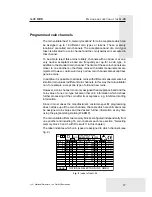
Page 17: ...accept one type of old and new coins However a coin channel is not only assigned the acceptance band and the coin value of one coin type but also other coin information which defines further processing of the coin after its acceptance e g inhibit and sorting information Since in most cases the manufacturer s customer specific programming does not take up all the coin channels channels which are st...

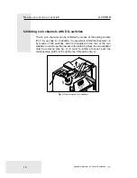
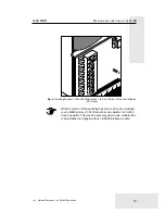
Page 18: ...8 In addition it is possible to inhibit the channels 1 8 by means of DIL switches which are situated on the rear of the coin validator In order to get free access to the switching block the coin validator must be removed see fig 3 In order to inhibit a channel push the corresponding switch to the right to the ON position fig 4 21614 Buxtehude Zum Fruchthof 6 Germany Close A B Fig 3 Removing the co...

Page 19: ...DIL switches 1 to 8 on the rear of the coin validator CPU card With DIL switch 9 of the switching block the G 46 can be switched over to MDB protocol if it is fitted with a coin validator G 40 4000 from 3 upwards This may be necessary when a new validator has to be installed in a changer with an old MDB interface module ...

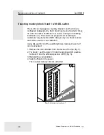
Page 20: ...i values sorting and inhibiting information etc The blocks are programmed according to customers requirements at NRI Always only one block is active and can be used for coin validation Using DIL switch 10 of the switching block memory block 0 or 1 can be activated 1 Remove the coin validator from the device at the top fig 3 2 For block 1 set DIL switch 10 into the right hand ON position for block ...

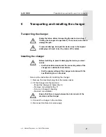
Page 21: ...ng to prevent damaging the device you must ensure that the interface module and the connecting cable of the changer are suitable for the machine that the supply voltage of the changer coincides with the specification given on the label Here are the instructions for installing the changer 1 Remove the machine s plug from the mains socket 2 Fit the changer into the machine Mount the changer 3 holes ...

Page 22: ...TRANSPORTING AND INSTALLING THE CHANGER G 46 MDB 22 National Rejectors Inc GmbH Buxtehude 21614 Buxtehude Zum Fruchthof 6 Germany Close A B Fig 6 Mounting the changer Fig 7 Removing the coin validator 1 ...

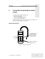
Page 23: ...tments PRO carry out service functions SER Connect the setting module to the socket 1 which is situated on the frontside of the changer at the top right fig 7 General key functions F E call up present adjustment of a selected function activate 1st sub function activate editing mode move cursor to the left reduce increase adjusted values leave function mode select function mode store values Fig 8 K...

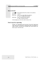
Page 24: ...arameters s chap 8 Programming functions SER mode Here you can find service functions s chap 9 Service functions Via the display you can check in which mode you are Basic steps of programming Primarily the programming basics describe the general programming steps However the instructions for changing the values are explained in a different chapter The subfunctions in the SER mode can be selected i...

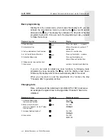
Page 25: ...hing digit by 1 4 Store value Press key E E twice F Display example Pro 1501 00000000 Pro 1501 00000000 Pro 1501 00000100 Pro 1501 00000100 Basic programming Starting from the normal mode which means the display is off you can activate the programming mode by pressing the F key two times and afterwards the E key The display then indicates Pro 04 which is the first programming function Once you are...

Page 26: ...ers of the tubes indicate an amount of money set the coin counters to zero by means of Ser 06 see chap 9 Service functions in Resetting the coin counters of the tubes Limit tube filling if necessary in Pro 25 see chap 8 Programming functions in Setting the maximum coin number per tube Filling tubes using the internal keyboard 1 Press key An acoustic signal confirms that you are in the tube filling...

Page 27: ...ty the display of the setting module now indicates the following see below 2 Insert coins The display changes the indication of the filling levels 3 Press key The display shuts down Meaning of the display for the filling levels Display Meaning Tube empty Tube not empty Tube full Contradictory messages from the tube filling sensors Programmed tube filling level reached When the display indicates ch...

Page 28: ...the right tube If you press a key for more than 4 seconds the coins will be paid out continuously Simply press any another key if you want to stop this process If in function 0401 the third digit from the right is set to 1 the machine control must enable inventory for emptying the tubes via the internal keyboard See description of the machine control Emptying tubes using the service function Ser 0...

Page 29: ...mode 3 00000000 While filling the tubes only accept coin to be sorted into tubes 1 reserved Transmit tube filling level incl security stock to the machine 1 Not enable inventory keys via the machine control 1 1501 Individual inhibiting of channels 1 8 1 00000000 channels 1 8 right to left 8 1 1502 Individual inhibiting of channels 9 16 1 00000000 channels 9 16 right to left 16 9 2101 Sensitivity o...

Page 30: ...left 5501 Coins to be sorted into middle left tube channels 1 8 1 00000000 channels 1 8 right to left 5502 Coins to be sorted into middle left tube channels 9 16 1 00000000 channels 9 16 right to left 5601 Coins to be sorted into middle right tube channels 1 8 1 00000000 channels 1 8 right to left 5602 Coins to be sorted into middle right tube channels 9 16 1 00000000 channels 9 16 right to left 5...

Page 31: ...theless and taken into consideration during the vending operation With the first place from the right hand side of function Pro 0401 you set whether the credit which cannot be displayed is to be added up or not Pro 0401 00000000 Add up credit which cannot be displayed 1 reset credit 0 Release of inventory keys via the machine control Pro 0401 Whether the inventory keys L ML MR R of the internal ke...

Page 32: ...lso the security stock is paid out Pro 0401 00000000 Security stock can be paid out with DISPENSE 1 Security stock cannot be paid out 0 Accept only tube coins when filling the tubes 0404 Use function Pro 0404 to set whether only those coins are to be accepted which are sorted into tubes or all coin types programmed while filling the tubes In the first case cash coins would be rejected Set the firs...

Page 33: ...coin channels can individually be inhibited by setting the digits assigned to the channels to 1 Pro 1501 00000000 Inhibit coin channel 1 1 Inhibit coin channel 2 1 Inhibit coin channel 3 1 Inhibit coin channel 4 1 Inhibit coin channel 5 1 Inhibit coin channel 6 1 Inhibit coin channel 7 1 Inhibit coin channel 8 1 Pro 1502 00000000 Inhibit coin channel 9 1 Inhibit coin channel 10 1 Inhibit coin chan...

Page 34: ... Setting the maximum coin number per tube Pro 25 In the sub functions 01 to 04 of Pro 25 you can set the maximum number of coins to be collected by each tube When the programmed number of coins is achieved for a tube all following coins for this tube will be led into the cash box Only when coins have been paid out from this tube is the tube able to collect coins again When 0 is programmed coins wi...

Page 35: ...er so that the security stock is not sent to the vending machine control if the machine control questions the tube filling level real filling level sent filling level security stock Setting the wake up time Pro 53 For coin changers in battery operation and with an external wake up line a time period can be set in function Pro 53 which specifies how long the coin changer remains switched on after h...

Page 36: ...Pro 5601 9 16 in tube M R Pro 5602 Channel 1 8 in tube R Pro 5701 9 16 in tube R Pro 5702 Example Left tube L is to collect 2 Euro coins and no longer 1 Euro coins 1 Euro coin is programmed in channels 4 normal 8 narrow 11 very narrow 2 Euro coin is programmed in channels 5 normal 9 narrow All channels of the 1 Euro coin are set to 1 Pro 5401 Pro 5401 10001000 00000100 8 1 16 9 All channels of the...

Page 37: ...ection Setting of the coin sorting to the tubes Pro 54 57 in this chapter The hopper is used if one coin type is particularly often paid out as change For the coin channel of both hoppers a sub function is assigned each see label in chap 4 Design and function of the G 46 for assignment coin type coin channel Coin channel for hopper 1 Pro 7001 Coin channel for hopper 2 Pro 7002 The hoppers must be ...

Page 38: ...ht tube 0604 Reset coin counter for right tube Resetting the coin counters of the tubes Ser 06 Before refilling the tubes e g after transporting the changer the four coin counters must be reset to zero For this proceed as follows Programming step 1 Select SER mode 2 Activate SER mode 3 Select function 4 Call up left tube 5 Reset coin counter 6 Call up middle left tube 7 Reset coin counter 8 Repeat...

Page 39: ...n payout slide and power supply unit not connected defective flat cable between payout slide and power supply unit sensor for final motor position defective motor control of power pack pcb defective Remedy if necessary refill machine if necessary clear expendable material e g coffee filter check Pro 15 and DIL switch and enable inhibited channel Read out error message via setting module see sectio...

Page 40: ...data for machine control cannot be transferred Remedy check all programming functions check machine check connecting cable to machine and to peripheral equipment check payout set by means of internal keyboard see previous section check connecting cable to machine Display Ab 01 Ab 02 Ab 03 Ab 04 Ab 05 Ab 06 Ab 07 Ab 08 Ab 09 Meaning coin rejected as measured values not lie within the acceptance ban...

Page 41: ...key press internal ML key press internal MR key press internal R key check all programming functions using PC software WinEMP check all programming functions using PC software WinEMP check all programming functions using setting module or PC software WinEMP check connecting cable The acceptance of a coin will also be indicated which is in the form of An x yy Here yy indicates the channel number an...

Page 42: ...string sensor check sum error in programming functions which despite being incorrectly adjusted only restricts G 46 function machine blocks G 46 Remedy check return lever check sensor check corresponding functions by means of setting module or PC software WinEMP check machine The following status messages can indicate problems with the machine Nevertheless the changer operates without fault ...

Page 43: ...ater from running into the device Otherwise the pcbs will be damaged Do not use solvents or scouring agents that can affect the plastic parts of the device 1 Switch off machine 2 Push lever 1 upwards and open coin validator see fig 9 3 Clean coin run way in coin validator with damp cloth ukewarm water plus detergent 4 Close coin validator 5 Switch on machine again Fig 9 Open the coin validator 1 ...

Page 44: ... front by means of the recesses 1 see fig 10 3 It is recommendable to unfasten the fastening screw 1 for the cash box channel on the right hand side of the housing see fig 11 4 Push one of the middle tubes downwards A and pull the tube next to it upwards B to lift the partition now remove tube towards the front C see fig 12 5 Push partition upwards with one hand A and if necessary remove the other...

Page 45: ...TS 45 National Rejectors Inc GmbH Buxtehude 1 Fig 10 Remove tube cover Fig 11 Unfasten fastening screw 1 2 5 0 6 C R A N E N A T I O N A L R E J E C 1 Fig 12 Dismount first tube 0 12V 9VA SEC 1 8 V A 0 8AT A B Fig 13 Dismount other tubes C B A ...

Page 46: ...the inner ones For the installation of the last tube the partition must be pushed upwards by pushing one of the adjacent tubes upwards 4 Check if all tubes are snapped into position at the top and at the bottom 5 Retighten the screw for the cash box channel on the right side of the housing 6 Insert tube cover on the payout set and push it into the housing with lateral locking levers slightly press...

Page 47: ...x channel see fig 15 4 Push side cover on the left side of the housing outwards and remove snapped in partition 1 see fig 16 5 Remove partition and cash box channel from the housing towards the front 6 Disconnect flat cable 1 between payout set and pcb see fig 17 7 Simultaneously push the right and left stop levers 2 inwards and remove the payout set 3 towards the front of the housing see fig 17 0...

Page 48: ...the interface module For the removal of the present pcb 1 Remove coin validator see chap 5 Installing the changer fig 5 2 Remove tubes see Exchanging tubes in this chapter 3 Remove partition and cash box channel see Exchanging the payout set in this chapter 4 Disconnect cable from pcb 5 If there is a dummy plug 1 remove it from the housing then remove cable from cable passages in the housing towar...

Page 49: ...B REPAIRING AND EXCHANGING COMPONENTS 49 National Rejectors Inc GmbH Buxtehude 110 120V 2 2 0 2 4 0 V 0 12V 9VA 0 8AT 0 120V 0 104V 0 120V 0 104V 0 12V 9VA SEC 18VA 0 8AT 1 2 3 Fig 18 Exchange interface module ...

Page 50: ...ight 380 0 mm width 133 5 mm depth 76 5 mm 80 mm with return lever pressed Mounting position vertical max deviation 2 Operating temperature 25 C to 70 C Air humidity max 90 Operating voltage 18 Volts 40 Volts DC Power consumption standby 3 5 VA max 15 VA Noise immunity The device meets the present requirements regarding noise immunity and noise emission according to the EC guidelines electromagnet...

Page 51: ...was were applied can be seen in the declaration of conformity The manufacturer must keep this declaration available for the monitoring authorities only for a minimum period of 10 years after the last product has been introduced to the market However upon request we can provide copies of this declaration for our customers Thefollowingdirectivesandtheirsubsequentchangescanbeappliedtoour devices 1 Th...

Reviews: