background image

-5-

MCTRL4K User‘s Manual

5  Main Interface

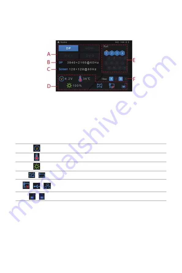
Switch on the controller and the main interface of its screen is shown as below:

A: Input state of signal sources. Blue indicates it has signal while gray indicates no  

signal;

B: Current input source and its resolution, frame rate. For example, the information 
of two DVI sources will be displayed alternately here when dual-link DVI is selected 
as input.

C: Width, height and frame rate of the LED display being configured;

D: Status, the meanings of each status icon are introduced as follows:

Supply voltage of mainboard core

Temperature inside the controller

Brightness of LED display

/

DVI1 and DVI2 are not synchronous/synchronous

/

/

Control interface, not connected/connected to USB port/ 

connected to Ethernet port 

/

Screen unlocked/locked

E: Connection status of Ethernet ports. Blue indicates that the connection is available 
and the port works as master control while gray indicates the port is not connected 
or the connection is unavailable. Mark on the upper left corner of the icon indicates 
that the connection is available and the port is in redundancy state.

F: Connection status of optical fiber ports. Blue indicates that the connection is 
available and the fiber port works as master control while gray indicates the port is 
not connected or the connection is unavailable. Mark on the upper left corner of the 
icon indicates that the connection is available and the port is in redundancy state.

XI'AN 

NOVASTAR 

TECH 

CO.,LTD.

Summary of Contents for MCTRL 4K

Page 1: ...XI AN N O VASTAR TECH CO LTD...

Page 2: ...prior written consent of NovaStar All rights are reserved Trademark is the registered trademark of NovaStar Safety Statement To avoid potential hazards please use this controller according to regulat...

Page 3: ...uctions may cause harmful interference to radio communications However there is no guarantee that interference will not occur in a particular installation If this equipment does cause harmful interfer...

Page 4: ...tion 4 5 Main Interface 5 6 Menu Operation 6 Step 1 Input Mode 6 Step 2 Input Resolution 6 Step 3 Quick Config 7 Step 4 Brightness Adjustment 8 Screen Settings 9 Display Control 9 Advanced Settings 10...

Page 5: ...ress and hold the button for 4 5 seconds to power off USB interface for connecting USB drives only unable to connect computers Operation screen Knob Pressing the knob indicates Enter or OK rotating th...

Page 6: ...t port 9 16 OPT3 is the backup of OPT1 OPT4 is the backup of OPT2 Control ETHERNET Control interface USB IN cascade input or connecting PC OUT cascading next unit GenLock IN Genlock synchronous signal...

Page 7: ...of interface intrduction and the figure below to connect requied hardwares Note Please disconnect the power of the equipment while connecting signal If it is required to control multiple MCTRL4K unit...

Page 8: ...select menus and press the knob to select current menu or enter submenus Select a menu with parameters and rotate the knob to adjust the parameters Please remember to press the knob again for confirma...

Page 9: ...I2 are not synchronous synchronous Control interface not connected connected to USB port connected to Ethernet port Screen unlocked locked E Connection status of Ethernet ports Blue indicates that the...

Page 10: ...used as two independent controllers and the loading capacity of each is up to 3840 2160 30Hz Now both DVI 1 and DVI 2 inputs are available and can be displayed on LED display simultaneously But only...

Page 11: ...view relevant chapter for detailed operations Step2 Enter the submenu of Quick Config and rotate the knob to get into other options for settings Main Brightness Input Settings Screen Settings Display...

Page 12: ...e are irregular cabinets cabinets with different sizes or irregular screens it is required to connect NovaLCT Mars for screen configuration c During data flow settings you can view the results of diff...

Page 13: ...e controller can be set in this option Display Control Main Brightness Input Settings Screen Settings Display Control Advanced Settings Communication Settings Language Display Control Normal Freeze Bl...

Page 14: ...ncy Primary Factory Reset Return to Home Screen Hardware Version Enable MAP Function When Map Function is enabled each of the cabinets will display the port number and Ethernet port number they belong...

Page 15: ...Factory Reset Return to Home Screen Hardware Version Enable Load Cabinet Files Cabinet File 1 Cabinet File 2 Cabinet File 3 4 Save cabinet files to hardware Alarm Threshold Set maximum and minimum va...

Page 16: ...ork Settings Config IPv4 Manually IP Address Subnet Mask Reset Communication modes include USB preferred and LAN Local Area Network preferred When both USB control interface and Ethernet control inter...

Page 17: ...OPT 4 Optical fiber port single mode and double fiber LC port 1310mm OPT1 is used for transferring the data of port 1 8 OPT2 is used for transferring the data of port 9 16 OPT3 is the backup channel...

Page 18: ...able to reach 3840x2160 60Hz Check whether the HDMI interface of video card is Standard 2 0 Precautions 1 At present this product only supports rectangular screens composed of cabinets with same size...

Reviews: