background image


16


S

ECTION

 5

C

 N

5.1 

C

 H

1. 

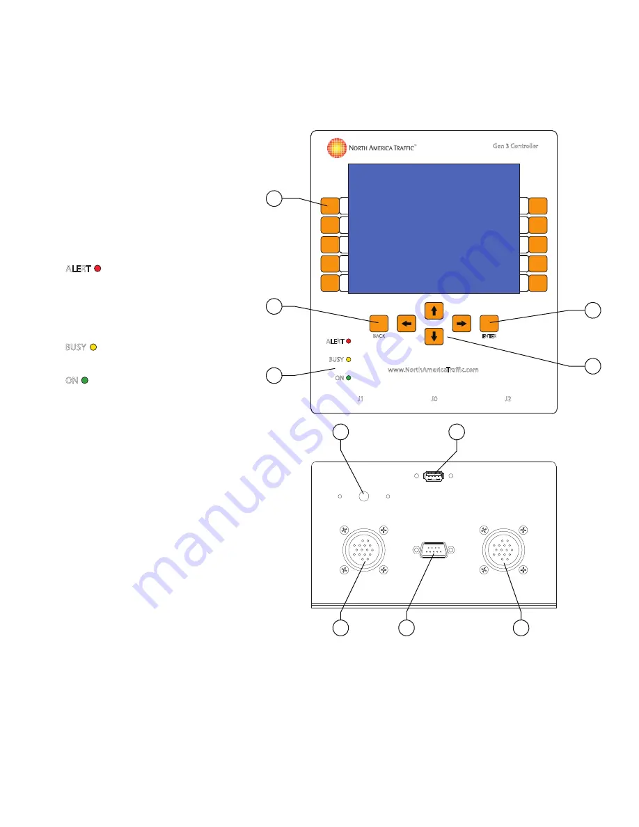
Soft Buttons

 – these 10 buttons  

  have no speci

fi

 c assigned values.  

  They will have a different value on  

 each 

screen. 

2. 

BACK Button

 – returns to the   

  previous menu screen.
3. 

L.E.D. Status Lights

:

ALERT

 - indicates whether there is a 

fault or error message. 

Note: Alert light will be illuminated for 

15 seconds following power down of 

the system.

BUSY

 - USB in use, settings being  

saved or copied, unit warming up.

ON

 - power indication.

4. 

ENTER Button

 – used to 


 con

fi

 rm a selected value or    

  open a paramater for editing.
5. 

Directional Buttons 

– allows the 

  user to toggle through menus,  


  various screens and cycling through  

  paramaters open for editing.
6. 

USB Port

 – used to import/export  

 software 

fi

 les, traf

fi

 c control plans  


  and fault/data logs.
7. 

J-Plugs (J1/J2)

 – I/O connections  

  to the terminal block by means of  


 wire 

harnesses.

8. 

Serial Port (J0)

 – connection to  

 radio 

transciever.

9. 

Speaker

 – emits audible noti

fi

 cation  

  to user when buttons are pressed.  


  Also emits loud beeping when  


  batteries are low.

6

7

8

7

9

ALERT

ON

BACK

BUSY

Gen 3 Controller

ENTER

J1

J2

J0

www.NorthAmericaTraffic.com

2

1

5

4

3

Under Side

Summary of Contents for RCF 2.4

Page 1: ...RCF 2 4 Automated Flagger Assistance Device Manual REV 08 02 10 22 THE LEADER IN TRAFFIC CONTROL SYSTEMS TM ...

Page 2: ... maintenance programs situations with limited manpower assigned to traffic control and other areas where the use of a mechanical device can help to save the lives of workers both in the work zone and those controlling traffic LIMITED RIGHTS Copyright 2022 by North America Traffic Inc All rights reserved including the right to reproduce this manual or portions thereof in any form whatsoever Informa...

Page 3: ... H 16 5 2 C S 17 5 3 SITE P 17 5 4 I S N 18 6 M Äç S Ù ÄÝ 19 6 1 C T 19 6 2 O 19 6 3 S O 21 6 4 H 21 7 S ãã Ä UÖ WÊÙ ZÊÄ 22 7 1 L 23 8 R Ê R ÃÊã 26 9 CÊÃÖ ã ãù MÊ 28 9 1 S C M G 3 28 9 2 O W G 1 29 10 D ã M Ä Ã Äã 30 10 1 F D L 30 10 2 S S D 31 10 3 S I E 32 11 OÖã ÊÄ EØç Öà Äã 33 11 1 R M S RMS 33 11 2 I A 33 12 CÊÃÃçÄ ã ÊÄÝ 35 12 1 R S 35 12 2 H 35 13 PÊó Ù SùÝã à IÄ ÊÙà ã ÊÄ 36 13 1 S 36 13 2 B...

Page 4: ...k right left turn signals hazard lights and brake lights for correct function Drive ahead about 10 feet and do a final walk around to ensure that all lock down points are secure safety chains are crossed under the tongue and latched securely and no tools or parts are sitting on the machine Note failure to ensure that all of the above precautions have been taken can result in injury and or death 1 ...

Page 5: ...s in contact with exposed skin and can cause blindness when in contact with your eye s Always wear protective goggles and gloves when working with batteries Electrical Burns An electrical short between the positive and negative terminals of the battery can cause severe burns and death even though the voltage is low 1 6 O H Prior to setting up the machine ensure there is sufficient clearance to rai...

Page 6: ...ce per mits the user to manually operate the AFAD unit s wirelessly from a safe distance MUTCD the Manual on Uniform Traffic Control Devices Contains regulatory information on the use of AFAD s in temporary traffic control situa tions on public roadways Refer to MUTCD section 6E 06 Red Yellow Lens Automated Flagger Assis tance Devices for further information regarding the use of AFAD s Phase a pha...

Page 7: ...r maximum capacity a full charge is achieved by using the 15 Amp smart charger 2 LED Signal Lamps and Housing The Signal Lamp is comprised of Light Emitting Diodes LED 12 diameter using a 24 VDC power supply and complies with ITE standards ITE certified polycarbonate housing with an aluminum backboard Standard ball cap visors extend over each LED lamp by 10 Back Lamp 4 amber LED lamp mounted on th...

Page 8: ...er external plug provided near cabinet door providing easy access for connection to a 120 VAC source Batteries receive some assisted energy supplied by the Solar Panel attached for more information see Solar Panel feature in this section Note For more detailed information pertaining to batteries charger and solar array refer to POWER SYSTEM INFORMATION SECTION 13 6 Trailer Section Components The T...

Page 9: ...required 3 Spare Tire Mount Optional add on item the spare tire assembly is secured for transport and deployment on the rear bumper between the two center locking tabs It is secured in place using two hitch pins 4 Tandem Tow Hitch Adapter Optional add on item The tandem tow hitch adapter permits two trailers to be towed in tandem ie Two pivot points The hitch adapter can be stored on the trailer w...

Page 10: ...to charge the batteries when unit is plugged into a 120 VAC power source 6 Solar Controller Regulator stabilizes and transmits the energy collected by the solar panel to the battery bank 7 Fuse Block fuses for all electrical functions 8 Isolated Power Distribution Studs the distribution point to which power from the batteries solar array and battery charger is connected to the signal control syste...

Page 11: ...en the two trailers and disconnect the running light cable 3 Return to the connection point between the two trailers Fully remove the linch pin from the hinged lock plates Rotate the released lock plate back so its out of the way Repeat these actions for the lock plate on the opposite side of the trailer Note If the locking plates are difficult to remove due to binding slightly raise or lower the ...

Page 12: ...the trailer Remove the cotter pin and slide the hitch pin out set aside 11 Position yourself parallel to the tongue and stand roughly in the middle of the length of the tongue Use care when removing the tongue as it is long and can tip fall to the side easily Lift using your knees and not your back 12 Grasp the tongue and slide it out to fully remove it from the trailer Place it in a secure locati...

Page 13: ...nsure temporary traffic control is operating prior to stepping onto the roadway Failure to do so may result in injury or death due to vehicular impact 8 Place the appropriate end in the gate arm sleeve at an angle 9 Align the holes of the gate arm and sleeve and insert the hitch pin to secure in place 10 Proceed to push the gate arm into the breakaway mechanism to complete deployment 4 4 T O Ensur...

Page 14: ...e trailers tow in a safe stable manner Improper hitch height can result in difficulty locking the trailers and cause trailer instability during transport 1 Retrieve the tongue and remove the hitch pin in the bumper 2 Slide the tongue fully into the insert in the bumper until it stops 3 Secure the tongue with the hitch pin Install the cotter pin into the hitch pin 4 Plug the running light cable fro...

Page 15: ...the rear unit until the coupling bar rests in the cradle 6 Insert two hitch pins to secure the coupling tube in the cradle 7 Connect the outer lock hinge plates by rotating them down and over the pins Install the linch pins to secure in place Note If the locking bars are difficult to connect due to binding slightly raise or lower the jacks as needed to until the plates freely move BE CAREFUL NOT T...

Page 16: ...f the rear trailer to the hitch adapter on the lead trailer 7 Lock the coupler and secure with the locking pin Manually lift the tongue to ensure it has been properly secured 8 Cross the safety chains under the tongue and connect them to the eyelets on the lead trailer s bumper 9 Connect the running light plug on the tongue to the receptacle on the bumper of the lead trailer 10 Ensure all jacks on...

Page 17: ...ER Button used to confirm a selected value or open a paramater for editing 5 Directional Buttons allows the user to toggle through menus various screens and cycling through paramaters open for editing 6 USB Port used to import export software files traffic control plans and fault data logs 7 J Plugs J1 J2 I O connections to the terminal block by means of wire harnesses 8 Serial Port J0 connection ...

Page 18: ...e accomplished either by unlocking the software via the OPTIONS menu or by selecting any option to edit Once selected a prompt will appear to enter the passcode After assigning a custom passcode if you wish to use additional unit s in conjunction with the current unit in operation you must reprogram the additional unit s to the SAME SITE PASSCODE Units operating with the same SITE PASSCODE will pr...

Page 19: ...DJUST TIMING WHEN NEEDED 4 4 4 MIN 27 27 YELLOW FLASH Once a soft button is selected i e Secondary 1 YELLOW FLASH Use the or directional buttons to increase or decrease the highlighted integer Lock parameters in memory by pressing ENTER ENTER pressing any other soft button or by shifting the selection to the opposing timing input Toggling Through the Unit Diagnostic Tab OPTIONS HELP PRI SEC1 PHZ U...

Page 20: ...dary 1 6 2 O GATE ARM FEB 01 17 09 53AM PROGRAM AFAD V HOME OPTIONS PG 1 BATTERY 24 0 VOLTS UNIT PRIMARY RADIO CHANNEL 03 RADIO SIGNAL DEFAULT FLASH RED PRESS START TO RESUME UNIT ID SITE LAYOUT RADIO CHANNEL INTRUSION ALARM NEXT PAGE PRIMARY LOCK SOFTWARE 03 ONE WAY ZONE TWO UNITS Unit ID used to designate each unit as either a primary or secondary machine Each unit will have a different designat...

Page 21: ...Unit Auto in single unit auto the unit will run automatically based on the timing settings Single Unit Pilot A single unit can be controlled A pilot car equipped with a radio remote can control the work zone without the need for a flagger A hardwired remote can also be employed Fault Logs used to log each fault that occurs with the date and time and type of fault Up to 10 000 faults are held in me...

Page 22: ... programmed to the same radio channel as the unit s by selecting SYNC RADIO REMOTE in the software and following the instructions on the screen 6 4 H The HELP feature is currently in development This section will be populated with the most common trouble shooting tips Currently all the input and output I O diagnostics can be viewed here OPERATOR SHALL BE FULLY TRAINED OPERATOR SHALL B OPTIONS FEB ...

Page 23: ...ary unit to continue setup Primary Setup 1 Proceed to Primary unit a Select OPTIONS b Set the UNIT ID to Primary c Choose the RADIO CHANNEL that was chosen on the secondary units d Select the SITE LAYOUT based on your work zone Refer to SECTION 7 1 LAYOUTS for a detailed list of all available layouts e Press the BACK button to return to the HOME screen and select TIMING i Edit Unit Phase timing RE...

Page 24: ...Manual Mode Primary Secondary 1 Manual Disclaimer Please consult the presiding traffic control manual to ensure proper work zone setup The following illustrations are not drawn to scale and are meant to be used as a guide in determining the proper setup of the signals In no way do these illustrations reflect the appropriate signal setup for all work zones Signal position and timing should be appro...

Page 25: ... 1 300 seconds HOME SCREEN SYNC RADIO REMOTE Follow instructions on screen SECONDARY 1 OPTIONS SETTINGS UNIT ID SECONDARY 1 RADIO CHANNEL 0 9 HARDWIRED PRIMARY OPTIONS SETTINGS UNIT ID PRIMARY RADIO CHANNEL 0 9 HARDWIRED SITE LAYOUT ONE WAY ZONE TWO UNITS GATE ARM GATE ARM ENABLE GATE ARM DELAY 0 10 seconds CONTROL MODE Choose MANUAL CHANGE TIMING SETTINGS RED CLEAR 1 600 seconds SOLID YELLOW 1 10...

Page 26: ...OME SCREEN SYNC RADIO REMOTE Follow instructions on screen TWO WAY ZONE MANUAL MODE SECONDARY 1 OPTIONS SETTINGS UNIT ID SECONDARY 1 RADIO CHANNEL 0 9 HARDWIRED PRIMARY OPTIONS SETTINGS UNIT ID PRIMARY RADIO CHANNEL 0 9 HARDWIRED SITE LAYOUT TWO WAY ZONE MANUAL GATE ARM GATE ARM ENABLE GATE ARM DELAY 0 10 seconds CONTROL MODE Choose MANUAL CHANGE TIMING SETTINGS RED CLEAR 1 600 seconds SOLID YELLO...

Page 27: ...must press and hold the button for 3 seconds until the LED illuminates Radio Remote Push Buttons Functions Manual Mode Pressing the Red button initiates ALL STOP Pressing the Green button will turn the Primary signal to YELLOW FLASH Pressing the Black button will turn the Secondary signal to YELLOW FLASH An ALL STOP must be performed prior to changing from a YELLOW FLASH at one unit to another Not...

Page 28: ... REMOTE 1 Press and hold the RED and BLACK buttons on the radio remote 2 Wait for prompt before releasing both buttons PRI SEC1 PHZ 1 4 Watt Radio WHITE WHITE 1 Watt REV 1 Radio BLACK WHITE 1 Watt Radio BLACK BLUE GREEN RED SIGNAL ACCEPTED PRESS AND HOLD BUTTON FOR 3 SECONDS TO SEND BEEP INDICATES LOW BATTERY KEEP REMOTE DRY MODEL NUMBER 500 1168 GREEN RED SIGNAL ACCEPTED BLACK PRESS AND HOLD BUTT...

Page 29: ...channel quanƟty Emergency Vehicle PreempƟon Railroad PreempƟon 9 1 S C M G 3 As with all generations of CU all the secondary units to be used in the network should be powered before the primary unit proper unit ID assigned refer to SECTION 9 2 OPERATING WITH GEN 1 for designation of proper unit ID s based on the generation of CU set to the same radio channel Refer to the specific unit s user field...

Page 30: ...t ID of SECONDARY 1 This unit ID structure has a bearing on which Gen 1 unit ID s are assigned based on the layout selected at the Gen 3 primary unit Refer to the chart below to determine which Gen 1 secondary unit ID s are required per the selected layout Note The numbered boxes indicate the assigned phase i e 1 phase 1 2 phase 2 SITE LAYOUT Pri S1B S2A S2B S3A S3B ONE WAY ZONE TWO UNITS 1 2 TWO ...

Page 31: ...and Data Logs 1 From the HOME screen select OPTIONS 2 Scroll to OPTIONS PAGE 2 and select FAULT LOGS 3 Use the NEXT PAGE or PREV PAGE soft buttons to scroll through the logs Exporting Logs 1 From the FAULT LOGS screen select EXPORT FAULT LOGS 2 A prompt will appear to insert the USB flash drive 3 Press EXPORT FAULT LOGS 4 The following screen will be displayed FEB 01 17 09 53AM PROGRAM MODEL V HOM...

Page 32: ... D additional data captured by system as it relates to the type of data log Columns A and C contain pertinent infomation by the end user 10 2 S S D Using the and directional buttons from the HOME screen will allow you to view the PHASE STATUS and DIAGNOSTIC screens for each unit in the network Press ENTER to view the selected tab Diagnostic Screen FEB 01 17 09 53AM PROGRAM AFAD V HOME DIAGNOSTIC B...

Page 33: ...other controllers This will save all program settings to the USB flash drive 1 From the OPTIONS menu select SOFTWARE IMPORT EXPORT Following the prompt on screen insert the USB flash drive 2 Select START IMPORT or START EXPORT when ready 3 Prompt to enter the system passcode will apprear Enter the passcode see SECTION 5 3 SYSTEM PASSCODE 4 Pop up status window will appear and notify when the expor...

Page 34: ... to the end user through the cellular network limited to areas of cellular cover age communicates from the AFAD to the end user through connec on to orbi ng satellites communica on anywhere in the world where the AFAD is deployed Fault Message Delivery text messages 4 max email 4 max text messages unlimited email unlimited end user must have email to text capability through their cellular carrier ...

Page 35: ...ular intrusion granting them time to exit the roadway The intrusion alarm sensor becomes inactive when a flash amber phase is served Once the unit transitions to an ALL STOP the intrusion sensor becomes active Should a vehicle intrude on a red signal while the gate arm is lowering the gate arm will retract This retract feature can be enabled or disabled in the software ...

Page 36: ...uctural steel Close proximity to radio stations airports and power lines Dip Switch Settings 1 Watt Radio Module 1 6 5 4 3 2 O N 12 2 H Where it is required Weak RSSI signal strength Less than 50 consistently see Systems Tray No line of sight i e inside a parking garage tunnels across large steel bridges under an overpass Cable Requirements Minimum Cable Specification Single twisted pair with a gr...

Page 37: ... remove snow or other large debris from the solar array 13 2 B The RCF 2 4 battery bank is comprised of wet cell lead acid 6 volt batteries wired for a 24 volt power supply This model comes equipped with a 4 battery configuration As an option sealed lead acid AGM batteries are available Autonomy The autonomy of the battery bank is defined as how many hours the units will operate the signal lamps a...

Page 38: ...minimum of 24 hours is required to bring the battery bank back to a full charge If using a generator refer to SECTION 13 4 GENERATOR USE for instruction Note intermittent charging for short periods of time will not provide adequate charge to the battery bank A continuous charge for a minimum of 24 hours is required Battery Threshold states Low 23 6 Normal operation continues but system warns user ...

Page 39: ...s can output high voltage spikes upon initial startup To protect the battery charger from such voltage spikes allow the generator to run for a few minutes after initial startup then make the connection to the battery charger ...

Page 40: ...at the tire was manufactured the 46th week of 2017 Proper Torque of Lug Nuts Ensure the lug nuts are torqued on a monthly basis Use a torque wrench The wheel lug nuts should be torqued to 60 ft lbs Note The lug nuts are torqued to spec at the factory Check and re torque after the first 10 miles 16 km 25 miles 40 km and again at 50 miles 80 km of travel This should also be done after every wheel re...

Page 41: ...nut as required Please contact North America Traffic for Instructions c Inspect All Locking Pins for Excessive Wear or Damage d Inspect the Tongue Draw Bar for Any Signs of Damage e Test the Running Lights for Proper Function Inspect the electrical contacts in all plugs and re ceptacles for signs of wear or corrosion Replace and components as required f Safety Chain Inspection Inspect safety chain...

Page 42: ...as been damaged Turn on Secondary x Change radio channel on Sec ondary x to match Primary A ach radio cable to radio to radio transmi or Set the dip switches as per diagram see Sec on 12 1 Replace antenna Replace radio cable TURN ON PRIMARY UNIT Secondary wai ng for commu nica ons to start a er power is turned on Primary is not turned on Primary is on radio channel is different than Secondary x Pri...

Page 43: ... transport truck between signals Radio channel is changed on one signal only Radio dip switches have been changed Radio cable is not a ached to the transmi er Radio cable has been dam aged Radio interference Move machines closer or use hardwired connec on Move machines to achieve line of sight or use hardwired connec on Increase drop out me see Sec on 6 4 Enable COMMUNICATION REGAIN see 6 4 Change...

Page 44: ... DEFAULT FLASH RED Default flashing as shown on Secondary machine Previous fault has cleared automa cally Machine Failure Press START bu on on Primary when ready to start program See Primary unit for instruc on DEFAULT FLASH RED PRESS START TO RESUME Default flashing as shown on Primary machine Previous fault has cleared automa cally Machine Failure Press START bu on on Primary when ready to start...

Page 45: ...ere displayed All LED lamps not connected Faulty controller Connect LED lamps Replace controller MALFUNCTION RESPONSE CHECK LAMP WIRING REPAIR MACHINE Malfunc on management system detected a ming fault on a lamp circuit LED lamp s not connected Faulty controller Connect LED lamp s Replace controller MALFUNCTION RESPONSE CONFLICTING LAMPS REPAIR MACHINE Malfunc on management system detected a confl...

Page 46: ...anel 500 0782 10A Solar Regulator 500 0673 6V FLA US2200 Battery 500 0149 15A 24V Battery Charger 500 0731 5A ATC Fuse 400 0419 10A ATC Fuse 500 0376 ST175 80R13 Tire w Wheel 500 1128 Fender 100 0076 Torsion Axle 1 200 lbs 500 1148 2 Ball Coupler 500 0235 Running Light Plug 7 Way 800 0227 Running Light Receptacle 7 Way 800 0226 8ft Aluminum Gate Arm Comp Alum Gate Arm 4 Red Wht 18 x 18 Orange Flag...

Page 47: ...46 SECTION 16 Part Name Part Number Quick Release Locking Pin 3 8 x 5 gate arm 300 0092 Quick Release Locking Pin 1 2 x 2 1 2 sign 500 1138 Gate Arm Breakaway Rubber Clamping Bushings 500 1136 ...

Reviews: