


82
Equipment installation and configuration
9
Plug the other jack of the NT8D46AL cable into the J5 of the
next slave system monitor in the direction away from the master
system monitor.
10
Test the system monitor daisy-chain by executing the STAT XSM
command in LD 37.
Ensure that every local and remote system monitor responds
to the master system monitor after the remote site is properly
installed and configured.
Note: If a system with the Carrier Remote IPE is shipped to a
site, steps 6 and 7 are completed in the factory.
--End--
Connecting multiple Local Carrier Interface cards to the system
monitor
Connect the Local Carrier Interface cards for system monitor daisy-chain in
the same sequence as the maintenance cables were daisy-chained for the
local MMI terminal and the local host SDI access for multiple Local Carrier
Interface cards.
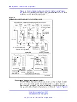
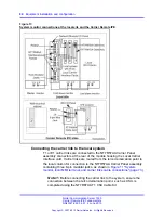
To daisy-chain the system monitor cables to multiple columns and multiple
NT7R51 Local Carrier Interface cards, refer to
connections at the local site and the Carrier Remote IPE" (page 84)
and
Appendix C,
Figure 30 "Local site system monitor connection diagram
(single and multiple LCI configuration)" (page 202)
, and follow the steps
in
Procedure 11 “Connecting multiple Local Carrier Interface cards to the
Procedure 11
Connecting multiple Local Carrier Interface cards to the system monitor
Step
Action
1
Starting from the top, as shown in
connections at the local site and the Carrier Remote IPE"
(page 84)
, plug the NT8D46AL cable 6-pin modular plug from
one NT7R58AA Maintenance Panel assembly 6-pin modular
jack J6 into the 6-pin modular jack J5 on the next NT7R58AA
Maintenance Panel assembly.
Note: Each NT7R58AA Maintenance Panel assembly
belongs to a different NT7R51 Local Carrier Interface card.
2
Repeat step 1 for all NT7R58AA Maintenance Panel assemblies.
Nortel Communication Server 1000
Carrier Remote IPE Fundamentals
NN43021-555 04.01
4 June 2010
Copyright © 2007-2010 Nortel Networks. All Rights Reserved.
.
Summary of Contents for Communication Server 100
Page 213: ......


