74
Equipment installation and configuration
Connecting a single Local Carrier Interface card to the MMI
terminal
Follow the steps in
Procedure 6 “Connecting a single Local Carrier
Interface card to the MMI terminal” (page 74)
to connect a Local Carrier
Interface card to the MMI terminal.
Procedure 6
Connecting a single Local Carrier Interface card to the MMI terminal
Step
Action
1
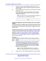
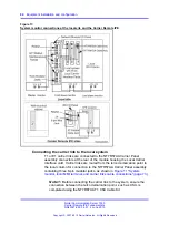
To connect a single NT7R51 Local Carrier Interface card to the
MMI terminal:
Note:
“Connection diagrams and external connectors pin
provides connection diagrams (
26 "Single LCI connection diagram (local site connections)"
(page 198)
) and pin assignment information for all external
connectors that connect to the SDI port, the MMI terminal, the
system monitor card, the external alarms, and the carrier links.
•
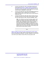
Plug the DB-9 male P1 connector at the common end of the
NT7R67DA Local External Maintenance Cable assembly into
the DB-9 female connector on the NT7R58AA Maintenance
Panel assembly.
•
Plug the DB-9 male P3 connector of the NT7R67DA cable
assembly into the DB-9 female connector of the NT7R66BA
MMI Cable.
•
Plug the DB-25 male end of the NT7R66BA MMI Cable
into the MMI terminal RS-232 connector. If it is necessary
to change the gender at the terminal, use the appropriate
compact gender changer.
•
To connect P3 DB-9 male connector of the NT7R67DA
Local External Maintenance Cable directly to the DB-9 male
RS-232 serial communication port of a laptop computer,
use an NT7R66BA MMI Cable and the appropriate compact
adapter.
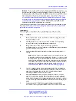
2
Make a MMI terminal connection using a modem:
•
If a modem is required to connect a distant MMI terminal to
the MMI port on the local I/O panel, plug the DB-9 female
Nortel Communication Server 1000
Carrier Remote IPE Fundamentals
NN43021-555 04.01
4 June 2010
Copyright © 2007-2010 Nortel Networks. All Rights Reserved.
.
Summary of Contents for Communication Server 100
Page 213: ......


