92
Equipment installation and configuration
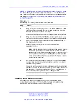
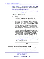
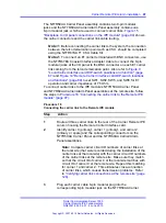
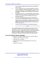
diagram (single RCI configuration)" (page 200)
for details. To install
the panel assemblies, follow the steps in
NT7R68AA Remote Carrier/Alarm Cable Assembly” (page 92)
Procedure 14
Installing the NT7R68AA Remote Carrier/Alarm Cable Assembly
Step
Action
1
Remove the back panel at the rear of the IPE module to be able
to access the I/O panel connector cutouts.
2
Identify the empty connector cutouts that are the appropriate size
for the panel assemblies.
Refer to
“Carrier Remote IPE Module I/O panel connector
for connector cutouts selection
recommendation.
3
Install the NT7R59AA Carrier Panel assembly into the
recommended connector cutout in the I/O panel.
Install it so that 8-pin modular jack tabs are positioned to the left
of the connectors, placing carrier 0 at the top of the NT7R59AA
Carrier Panel assembly and carrier 1 at the bottom.
Tighten the retaining screw.
4
Install the NT7R60AA Carrier/Alarm Panel assembly into the
recommended J5 empty connector cutout in the I/O panel.
Tighten the retaining screw. This panel contains an 8-pin
modular jack for carrier 2 at the bottom and a DB-15 HD female
auxiliary alarm (external alarm) connector at the top of the panel
assembly.
5
Plug the P1 24-pin block connector of the NT7R68AA Remote
Carrier/Alarm Cable assembly into the connector on the IPE
Module’s backplane.
--End--
Installing the NT7R68BA Remote Maintenance Cable Assembly
The NT7R68BA Remote Maintenance Cable Assembly consists of the
NT7R68GA cable and NT7R61AA Maintenance Panel assembly.
Before plugging the cable into the IPE module backplane, install the
NT7R61AA Maintenance Panel assembly into the connector cutout
on the I/O panel at the rear of the IPE module. Refer to
"Backplane to I/O panel connections on the IPE module" (page 94)
and
Figure 28 "Remote Carrier IPE module connection diagram (single RCI
Nortel Communication Server 1000
Carrier Remote IPE Fundamentals
NN43021-555 04.01
4 June 2010
Copyright © 2007-2010 Nortel Networks. All Rights Reserved.
.
Summary of Contents for Communication Server 100
Page 213: ......

