


December 2006
1005r server description
1005r Server Hardware Installation
19
Back panel controls and features
The following diagram shows the back panel controls and features. On
the right are the AC power supply banks. The PCI card brackets are in
the middle of the back panel while the connectors and ports are along the
bottom and left side.
Figure 2: Back panel controls and features
I
ID LED
T
Hard drive 0 pull handle
J
NIC activity LED
U
Hard drive 0 release lever
K
Status LED
Label
Control or feature
Label
Control or feature
A
DB15 Telco alarm
connector (not used)
H
RJ45 NIC 1 connector
B
PCI low-profile card
brackets. Numbered (1, 2, 3)
from top to bottom.
I
RJ45 NIC 2 connector
Label
Control or feature
Label
Control or feature
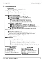
Summary of Contents for CallPilot 1005r
Page 6: ...Standard 1 06 6 CallPilot ...
Page 8: ...8 CallPilot Publication history Standard 1 06 ...
Page 10: ...Task List Standard 1 06 10 CallPilot ...
Page 12: ...Contents Standard 1 06 12 CallPilot ...
Page 34: ...1005r server description Standard 1 06 34 CallPilot ...
Page 58: ...Installing the server and peripheral devices Standard 1 06 58 CallPilot ...
Page 72: ...Index Standard 1 06 72 CallPilot ...
Page 73: ......


