


72
7.2
SCAN OPTIONS TAB
•
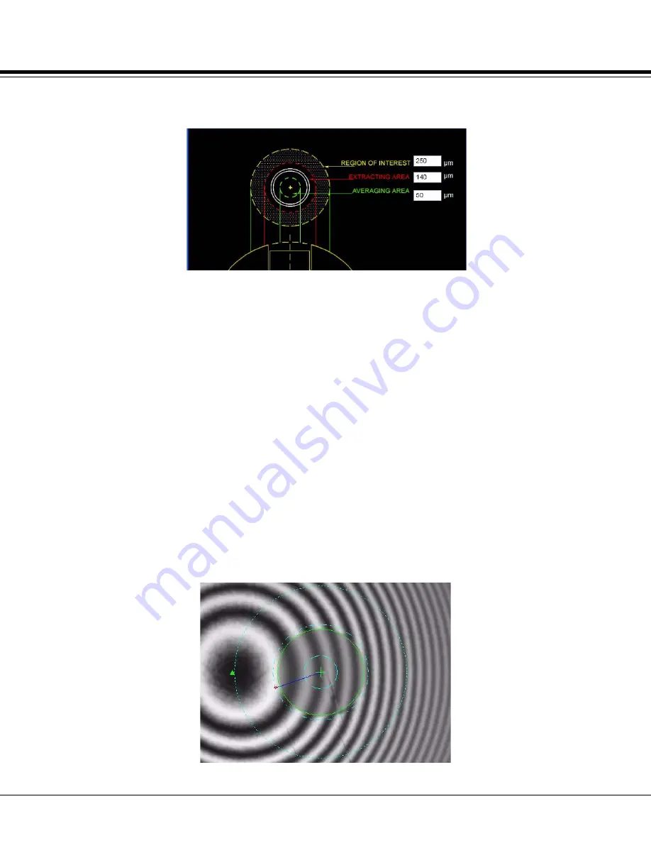
Show Regions
: Select this option to show the measurement areas (dashed
circles in illustration below) as overlays on the Live View after scan
completion.
REGION OF INTEREST
(ROI): Specifies the diameter in microns of a
circular window from the center of the fiber to the outer most ring in the
figure above. The allowable range for the ROI is from 170 to 500µm
(Default value: 250µm). The ROI is used to calculate the Radius of
Curvature. To obtain the fitting area as defined by the IEC, the extraction
area is subtracted from the ROI.
EXTRACTION AREA:
Specifies a circular portion within the ROI (centered
at the fiber center and includes the fiber end face region and the adhesive
region) which will be extracted from the data. This extracted data will not be
used in the quantitative analysis of the Radius of Curvature. (Default value:
140 µm)
AVERAGING AREA
: Specifies the averaging area in the center of the fiber
used to calculate the fiber height. (Default value: 50 µm). NOTE: For
measuring Multimode-fiber connectors, the User must change this
parameter before measurement to 100 µm (or load a previously saved
Settings file with that value already preconfigured).
Live Image with regions overlaid:
Summary of Contents for Connect-Chek CC6000
Page 2: ......
Page 3: ......
Page 4: ......
Page 13: ......
Page 14: ......
Page 16: ......
Page 28: ...C H A P T E R 2 28 SYSTEM PREPARATION...
Page 40: ...C H A P T E R 3 40 NCC PROGRAM...
Page 42: ...42 3 1...
Page 43: ...C H A P T E R 4 43 MENU BAR FUNCTIONS...
Page 45: ...45 4 1...
Page 55: ...55 4 4...
Page 56: ...56 C H A P T E R 5 TOOLBAR FUNCTIONS...
Page 64: ...64 C H A P T E R 6 IMAGE TABS...
Page 67: ...C H A P T E R 7 67 CONTROL TABS...
Page 75: ...75 7 2 SCAN OPTIONS TAB...
Page 82: ...82 7 4 REFERENCE TOOL CALIBRATION...
Page 92: ...C H A P T E R 9 92 APPENDIX...
Page 104: ...104 9 3 SHIPPING INSTRUCTIONS...


