background image

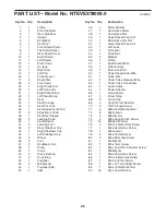
25

1

1

Frame

2

1

Front Stabilizer

3

1

Rear Stabilizer

4

1

Upright

5

1

Handlebar

6

1

Seat Post

7

1

Front Shield Cover

8

1

Top Shield Cover

9

1

Rear Shield Cover

10

1

Right Shield

11

1

Left Shield

12

1

Pivot Cover

13

1

Console

14

1

Right Pad

15

1

Left Pad

16

1

Pulse Sensor

17

2

Pedal Disc

18

2

Disc Cover

19

1

Right Crank Arm

20

1

Left Crank Arm

21

1

Right Pedal/Strap

22

1

Left Pedal/Strap

23

1

Seat

24

1

Seat Carriage

25

2

Seat Post Cap

26

1

Seat Adjustment Knob

27

2

Adjustment Knob

28

1

Seat Post Sleeve

29

2

Leveling Knob

30

1

Seat Bracket

31

2

Leveling Foot

32

2

Rear Stabilizer Cap

33

1

Right Stabilizer Cap

34

1

Left Stabilizer Cap

35

2

Wheel

36

2

Foot

37

2

Handlebar Cap

38

1

Pulley

39

1

Crank

40

2

Crank Bearing

41

2

Snap Ring

42

1

Flywheel

43

2

M8 Washer

44

1

Flywheel Axle

45

1

Idler

46

1

Motor Bracket

47

1

Resistance Motor

48

1

Resistance Disc

49

1

Upper Resistance Arm

50

1

Resistance Arm Nut

51

1

Lower Resistance Arm

52

1

Arm Lock

53

1

C-magnet

54

1

Drive Belt

55

2

Magnet

56

1

Clamp

57

1

Reed Switch/Wire

58

1

Wire Harness

59

1

Extension Wire

60

1

Power Receptacle/Wire

61

1

Pulse Wire

62

1

Chest Pulse Receiver/Wire

63

1

Chest Pulse Transmitter

64

1

Audio Cable

65

1

Power Adapter

66

1

Plug Adapter

67

1

Chest Strap

68

2

Crank Cap

69

2

Upright Pivot Bushing

70

2

5/16" Flange Screw

71

4

M8 x 20mm Button Bolt

72

8

M8 Locknut

73

2

M8 Jam Nut

74

4

M8 x 20mm Patch Screw

75

12

M8 Split Washer

76

4

M10 x 95mm Patch Screw

77

1

M6 x 65mm Hex Screw

78

1

M6 Locknut

79

4

M4 x 12mm Screw

80

2

M6 x 8mm Hex Screw

81

1

M5 Washer

82

1

M5 x 7mm Screw

83

1

M6 x 14.67mm Shoulder Screw

84

1

M6 Washer

85

1

M6 x 20mm Hex Screw

86

1

M10 x 65mm Hex Screw

87

1

M3.5 x 12mm Screw

88

1

M4 x 12.7mm Bright Screw

89

1

M6 x 70mm Barrel Nut

90

16

M4 x 16mm Screw

Key No. Qty.

Description

Key No. Qty.

Description

PART LIST—Model No. NTEVEX78009.0

R0909A

Summary of Contents for C7 Zl Bike

Page 1: ...Serial No Write the serial number in the space above for future reference USER S MANUAL www iconeurope com QUESTIONS If you have questions or if there are missing parts please contact us Call 08457 089 009 From Ireland 053 9236102 Website www iconsupport eu E mail Visit www iconsupport eu Write ICON Health Fitness Ltd c o HI Group PLC Express Way Whitwood West Yorkshire WF10 5QJ UK ...

Page 2: ... location shown Note The decal s may not be shown at actual size TABLE OF CONTENTS WARNING DECAL PLACEMENT 2 IMPORTANT PRECAUTIONS 3 BEFORE YOU BEGIN 4 ASSEMBLY 5 HOW TO USE THE CHEST PULSE SENSOR 12 HOW TO USE THE EXERCISE CYCLE 13 MAINTENANCE AND TROUBLESHOOTING 22 EXERCISE GUIDELINES 24 PART LIST 25 EXPLODED DRAWING 27 ORDERING REPLACEMENT PARTS Back Cover NordicTrack is a registered trademark ...

Page 3: ...le on a level surface with a mat beneath it to protect the floor or carpet Make sure that there is at least 2 ft 0 6 m of clearance around your exercise cycle 6 Inspect and properly tighten all parts regu larly Replace any worn parts immediately 7 Keep children under age 12 and pets away from the exercise cycle at all times 8 Wear appropriate clothes while exercising do not wear loose clothes that...

Page 4: ...use the exercise cycle If you have questions after reading this manual please see the front cover of this manual To help us assist you note the product model number and serial number before contacting us The model number and the location of the serial number decal are shown on the front cover of this manual Before reading further please familiarize yourself with the parts that are labeled in the d...

Page 5: ... materials Do not dispose of the packing materials until assembly is completed In addition to the included tool s assembly requires a Phillips screwdriver an adjustable wrench and a rubber mallet As you assemble the exercise cycle use the drawings below to identify small parts The number in parentheses below each drawing is the key number of the part from the PART LIST near the end of this manual ...

Page 6: ...zer 3 to the Frame 1 with two M10 x 95mm Patch Screws 76 2 Attach the Front Stabilizer 2 to the Frame 1 with two M10 x 95mm Patch Screws 76 1 2 To make assembly easier read the information on page 5 before you begin 3 2 76 76 1 1 ...

Page 7: ...he Seat Post 6 upward or downward slightly to make sure that the Adjustment Knob 27 is engaged in one of the adjust ment holes in the Seat Post Then tighten the Adjustment Knob 4 Orient the Seat 23 and the Seat Carriage 24 as shown Attach the Seat 23 to the Seat Carriage 24 with four M8 Locknuts 72 and four M8 Split Washers 75 Slide the Seat Carriage 24 onto the Seat Post 6 Then slide the Seat Car...

Page 8: ... an M6 x 60mm Barrel Nut 93 through the lower bracket on the Handlebar 5 Tighten an M6 x 16mm Patch Screw 97 into the end of the Barrel Nut 5 59 5 43 43 97 97 93 89 4 Grease Avoid pinching the Extension Wire 59 6 90 90 6 While another person holds the Console 13 near the Handlebar 5 connect the console wires to the Extension Wire 59 the Pulse Wire 61 and the Chest Pulse Wire 62 Insert the excess w...

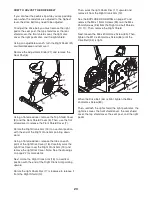
Page 9: ...ar Attach the Pivot Cover 12 to the Handlebar 5 with four M4 x 16mm Screws 90 Pivot the Handlebar 5 until the hole in the Handlebar is aligned with an adjustment hole in the Upright 4 Tighten an Adjustment Knob 27 into the Handlebar 5 and an adjustment hole in the Upright 4 Make sure that the Adjustment Knob is engaged in one of the adjustment holes 4 12 90 90 90 27 Hole Adjustment Holes 5 ...

Page 10: ...1 Avoid pinching the wires 9 Identify the Right Pedal 21 which is marked with an R Using an adjustable wrench firmly tighten the Right Pedal 21 clockwise into the Right Crank Arm 19 Tighten the Left Pedal not shown counter clockwise into the Left Crank Arm not shown IMPORTANT Tighten both pedals as firmly as possible After using the exercise cycle for one week retighten the pedals For best perform...

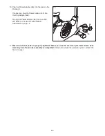
Page 11: ... over after assembly is completed Place a mat under the exercise cycle to protect the floor or carpet 10 Plug the Power Adapter 65 into the jack on the Frame 1 If necessary plug the Power Adapter 65 into the Plug Adapter 66 To plug the Power Adapter 65 into an outlet see HOW TO PLUG IN THE POWER ADAPTER on page 13 66 65 1 ...

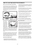
Page 12: ...n a warm dry place Do not store the chest pulse sensor in a plastic bag or other container that may trap moisture Do not expose the chest pulse sensor to direct sun light for extended periods of time or to temperatures above 122 F 50 C or below 14 F 10 C Do not excessively bend or stretch the sensor unit when using or storing the chest pulse sensor Clean the sensor unit using a damp cloth never us...

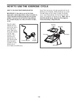
Page 13: ...e plug adapter Then plug the plug adapter into an appropriate outlet that is properly installed in accor dance with all local codes and ordinances Note The console can also be operated with four D batteries not included alkaline batteries are recom mended Remove the screws remove the battery cover insert the batteries into the battery compart ments and reattach the battery cover Make sure to orien...

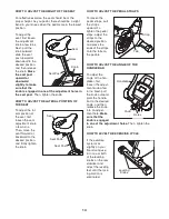
Page 14: ... to the desired position and firmly tighten the knob HOW TO ADJUST THE PEDAL STRAPS To loosen the pedal straps pull the straps upward To tighten the pedal staps adjust the straps to the desired position and press the ends of the straps onto the tabs on the pedals HOW TO ADJUST THE ANGLE OF THE HANDLEBAR To adjust the angle of the han dlebar first loosen the adjust ment knob a few turns Next pull t...

Page 15: ...e resistance of the pedals and prompt you to vary your pedaling speed to keep your power output near a target level The console features the iFit interactive workout sys tem which enables the console to accept iFit cards containing workouts designed to help you achieve specific fitness goals For example lose unwanted pounds with the 8 week Weight Loss workout iFit workouts control the resistance o...

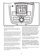
Page 16: ... pedaling and change the resistance of the pedals as desired As you pedal change the resistance of the pedals by turning the resistance dial To increase the resistance turn the resistance dial clockwise to decrease the resistance turn the resistance dial counterclockwise Note After you change the resistance it will take a moment for the pedals to reach the selected resistance level 4 Follow your p...

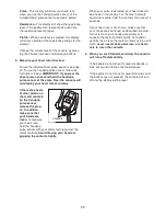
Page 17: ...on the handgrip pulse sensor remove the plas tic In addition make sure that your hands are clean To measure your heart rate hold the handgrip pulse sensor with your palms resting against the metal contacts Avoid moving your hands or gripping the contacts tightly When your pulse is detected your heart rate will be shown in the display For the most accurate heart rate reading hold the contacts for a...

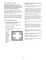
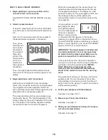
Page 18: ...ppear in the display for a few seconds to alert you The next segment of the pro file will begin to flash and the pedals will automatically adjust to the resistance level for the next segment As you exercise you will be prompted to keep your pedaling speed near the target speed for the current segment When an upward arrow or the word FASTER appears in the display increase your speed When a downward...

Page 19: ...ent Note The same target heart rate may be programmed for consecutive seg ments During the workout the console will regularly com pare your heart rate to the target heart rate for the current segment of the workout If your heart rate is too far below or above the target heart rate the resistance of the pedals will automatically increase or decrease to bring your heart rate closer to the target hea...

Page 20: ...ents One resistance level and one target watts level are programmed for each seg ment Note The same resistance level and or target watts level may be programmed for consec utive segments The workout profile will show your progress see the drawing at the left The flashing segment of the profile represents the current segment of the workout The height of the flashing segment indi cates the resistanc...

Page 21: ... the iFit card in a secure place HOW TO USE THE SOUND SYSTEM To play music or audio books through the consoleʼs sound system while you exercise plug the included audio cable into the jack on the console and into a jack on your MP3 player or CD player make sure that the audio cable is fully plugged in Next press the play button on your MP3 player or CD player Adjust the volume level using the volum...

Page 22: ...o a vertical position with the end of the Left Crank Arm pointing downward Using a flat screwdriver release the tabs on each point of the left Disc Cover 18 Carefully work the left Disc Cover over the Left Crank Arm 20 and remove the left Disc Cover Next rotate the Left Crank Arm 20 to a vertical position with the end of the Left Crank Arm pointing upward Rotate the left Pedal Disc 17 clockwise to...

Page 23: ... tabs on each point of the right Disc Cover 18 Carefully work the right Disc Cover over the Right Crank Arm 19 and remove the right Disc Cover Note See the drawings on page 22 for more detail Next rotate the Right Crank Arm 19 to a vertical position with the end of the Right Crank Arm pointing upward Rotate the right Pedal Disc 17 clockwise to release it from the Right Shield 10 Then work the righ...

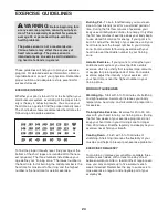
Page 24: ...f your goal is to strengthen your cardiovascular system you must perform aerobic exercise which is activity that requires large amounts of oxygen for prolonged periods of time For aerobic exercise adjust the intensity of your exercise until your heart rate is near the highest number in your training zone WORKOUT GUIDELINES Warming Up Start with 5 to 10 minutes of stretching and light exercise A wa...

Page 25: ...esistance Motor 48 1 Resistance Disc 49 1 Upper Resistance Arm 50 1 Resistance Arm Nut 51 1 Lower Resistance Arm 52 1 Arm Lock 53 1 C magnet 54 1 Drive Belt 55 2 Magnet 56 1 Clamp 57 1 Reed Switch Wire 58 1 Wire Harness 59 1 Extension Wire 60 1 Power Receptacle Wire 61 1 Pulse Wire 62 1 Chest Pulse Receiver Wire 63 1 Chest Pulse Transmitter 64 1 Audio Cable 65 1 Power Adapter 66 1 Plug Adapter 67 ...

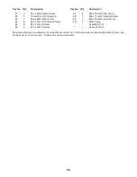
Page 26: ...ts are not illustrated 91 2 M4 x 5mm Bright Screw 92 2 Handlebar Pivot Bushing 93 1 M6 x 60mm Barrel Nut 94 6 M4 x 19mm Flat Head Screw 95 8 M4 x 19mm Screw 96 2 M4 x 25mm Screw 97 2 M6 x 16mm Patch Screw 98 3 M8 x 17mm Flat Head Screw 99 2 M4 x 16mm Flange Screw 100 2 Wire Clamp Assembly Tool Userʼs Manual Key No Qty Description Key No Qty Description ...

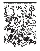
Page 27: ...42 44 45 46 47 48 49 50 51 52 53 54 55 55 56 57 58 59 60 61 62 63 64 65 66 67 68 68 69 92 70 70 71 71 72 72 72 73 73 74 74 74 75 75 76 76 77 78 79 80 81 82 83 84 85 86 87 90 89 91 90 90 90 99 95 90 95 90 95 95 95 95 95 96 96 94 94 94 90 90 88 75 75 90 74 90 90 90 75 30 98 43 43 97 93 5 41 100 100 27 EXPLODED DRAWING Model No NTEVEX78009 0 R0909A ...

Page 28: ...elp us assist you be prepared to provide the following information when contacting us the model number and serial number of the product see the front cover of this manual the name of the product see the front cover of this manual the key number and description of the replacement part s see the PART LIST and the EXPLODED DRAWING near the end of this manual ...

Reviews: