BU 0750 GB
Technical design subject to change
107
Parameter
Setting value / Description / Notes
Parameter set Available with option
P458
mode analogue out
P
MLT
0 ... 1
[ 0 ]
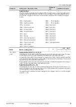
The mode of the analogue output of the Multi- I/O modules (SK CU1-MLT, SK CU1-MLT
20mA, optional) is adjustable.
0...20mA / 0...10V
4...20mA / 2...10V
P460
Watchdog time
P
Always available
0.0 / 0.1 ...
250.0 s
[ 10.0 ]
0.1 ... 250.0
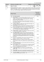
= The time interval between the signals to be provided to the watchdog can be assigned
as a function to the digital inputs P420 to P425. If no pulse is received within the period specified, the
FI disconnects the output and generates an E012 error message.
0.0 =
Customer error function
: As soon as a low-to-high edge is received at a digital input
(funct. 18), the FI effects a disconnection while generating an E012 error message.
P480
.. - 01
...
.. - 08
Funct. BusIO In Bit 1...8
Always available
0 ... 48
[ 0 ]
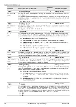
The system will process the bus I/O In-bits like the information received via the digital inputs. The same
functions can be assigned to them (P420...425).
[01] =
Bus I/O In-bit 1
[02] =
Bus I/O In-bit 2
[03] =
Bus I/O In-bit 3
[04] =
Bus I/O In-bit 4
[05] =
Bus I/O initiator 1
[06] =
Bus I/O initiator 2
[07] =
Bus I/O initiator 3
[08] =
Bus I/O initiator 4
For the functions the bus In-bits are able to assume please consult the table of potential functions to be
assigned to the digital inputs included in the description of parameters P420...P425.
For more detailed information please refer to the manual of the respective bus system.
P481
.. - 01
...
.. - 08
Funct-BusIO Out Bit 1...8
Always available
0 ... 38
[ 0 ]
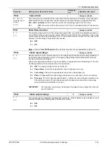
The control system will process the bus I/O Out-bits like multi-function relay outputs. Accordingly they
can be used to execute the same functions (P434...443).
[01] =
Bus I/O Out-bit 1
[02] =
Bus I/O Out-bit 2
[03] =
Bus I/O Out-bit 3
[04] =
Bus I/O Out-bit 4
[05] =
Bus I/O actuator 1
[06] =
Bus I/O actuator 2
[07] =
marker 1
[08] =
marker 2
For the functions the bus Out-bits are able to assume please refer to the table of relay functions in-
cluded in parameter P434.
For more detailed information please consult the manual of the respective bus system.
P482
.. - 01
...
.. - 08
Norm. BusIO Out Bit 1...8
Always available
-400 … 400 %
[ 100 ]
Adjustment of the limit values applicable to the relay functions / bus Out-bits. If a negative value is se-
lected, the output function is put out in a negated fashion.
If the values set are positive, the relay contact will close when the limit value is reached. If the values
set are negative, the relay contact will open when the limit value is reached.
P483
.. - 01
...
.. - 08
Hyst. BusIO Out Bit 1...8
Always available
1 … 100 %
[ 10 ]
Is the difference provided between the operate point and the release point to avoid any oscillation of
the output signal.


