NORDAC SK 750E Manual
118
Technical design subject to change
BU 0750 GB
Parameter
Setting value / Description / Note
Parameter
set
Available with option
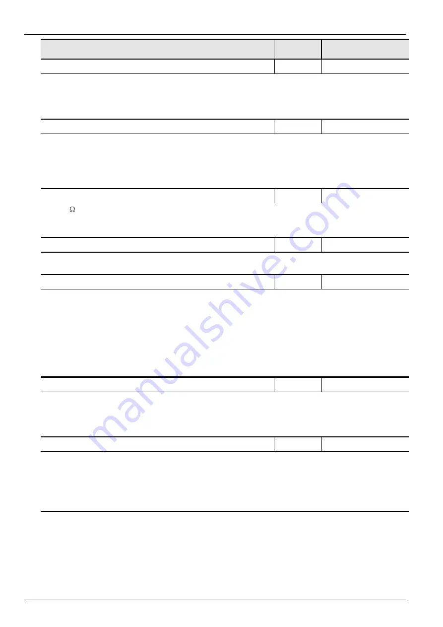
P554
Chopper min.
Always available
65 … 100 %
With this parameter the option of limiting the maximum resistor efficiency by hand can be pro-
grammed. The on-period of the resistor for chopping (degree of modulation) must not exceed the de-
fined limit. When the duty factor equals this value, the FI will de-energize the resistor whatever the
amount of the D.C. link voltage will be at the time.
Otherwise the resulting overvoltage would bring about a disconnection of the output by the inverter.
P555
P-limit chopper
Always available
5 ... 100 %
[ 100 ]
With this parameter the option of limiting the maximum resistor efficiency by hand can be pro-
grammed. The on-period of the resistor for chopping (degree of modulation) must not exceed the de-
fined limit. When the duty factor equals this value, the FI will de-energize the resistor whatever the
amount of the D.C. link voltage will be at the time.
Otherwise the resulting overvoltage would bring about a disconnection of the output by the
inverter.
P556
Braking resistor
Always available
3 ... 400
[ 120 ]
Setting the braking resistor capacity which is a value affecting the maximum braking pwoer allowed
in view of protecting the resistor.
When the maximum continuous rating (P557) is reached, the inverter trips with an I
2
t limit error sig-
nal (E003).
P557
Brake resistor rating
Always available
0.00 ... 100.00 kW
[ 0.00 ]
Continuous rating of the braking resistor. Enables calculation of the maximum braking power.
0.00
= Monitoring function switched off
P558
Flux delay
P
Always available
0/ 1/ 2...500 ms
[ 1 ]
For ISD control to work properly, a magnetic field must be present in the motor. That is why a direct
current is fed to the motor prior to starting. The duration of this interval depends on the motor size
and is automatically set in the factory.
For time-critical applications the default magnetisation time can be modified or even deactivated.
0 =
OFF
1 =
calculated automatically
2...500 = as selected
Note:
If too little time is allowed for a magnetic field to build up, this may affect the dynamic re-
sponse of the motor and torque development
during the starting period.
P559
DC Run-on time
P
Always available
0.00 ... 5.0 s
[ 0.50 ]
When the motor has been ramped down following a stop signal, it is fed a short-term direct current
to bring the drive to a complete halt. The length of time for which a direct current should be supplied
depends on the mass moment of inertia and can be set in this parameter.
The amount of direct current required depends on the way deceleration has been executed (ISD cur-
rent control) or on the percentage of the static boost involved (linear characteristic).
P560
Save on EEPROM
Always available
0 ... 1
[ 1 ]
0 =
Any changes of the parameter settings will be lost when the inverter is disconnected from
the mains.
1 =
Any changes of a parameter setting are automatically written to the EEPROM. Thus they
are preserved even when the inverter is disconnected from the mains.
NOTE:
If USS communication is used to effect parameter changes, be careful not to exceed the
maximum number of write cycles (100.000 x).
7.8 PosiCon
A description of the parameters
P6xx
is provided in the
BU 0710
Operating Instructions.
These parameters are not available unless the optional PosiCon
SK XU1-POS
positioning control module is
used.


