SK 500E – Users Manual for Frequency Inverters
138
BU 0500 EN-3021
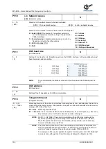
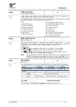
P518
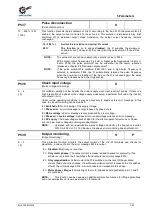
Skip frequency 2
(Skip frequency 2)
S
P
0.0 ... 400.0 Hz
{ 0.0 }
The output frequency around the set frequency value (P519) is skipped.
This range is transmitted with the set brake and acceleration ramp; it cannot be continuously
supplied to the output. Frequencies below the absolute minimum frequency should not be set.
0 =
Skip frequency inactive
Pos: 325 /Anleitungen/Elektronik/FU und Starter/5. Parameter/Parameterauflistung (P000 ...)/P500-P599/Parameter P519 – Ausblendbereich 2 @ 0\mod_1328092748353_388.docx @ 11318 @ @ 1
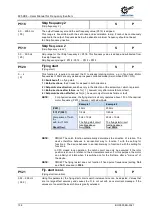
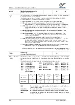
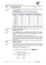
P519
Skip freq. area 2
(Skip frequency area 2)
S
P
0.0 ... 50.0 Hz
{ 2.0 }
Skip range for the >Skip frequency 2< P518. This frequency value is added and subtracted from
the skip frequency.
Skip frequency range 2: P518 - P519 ... P518 + P519
Pos: 326 /Anleitungen/Elektronik/FU und Starter/5. Parameter/Parameterauflistung (P000 ...)/P500-P599/Parameter P520 – Fangschaltung @ 0\mod_1328092790587_388.docx @ 11341 @ @ 1
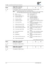
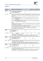
P520
Flying start
(Flying start)
S
P
0 ... 4
{ 0 }
This function is required to connect the FI to already rotating motors, e.g. in fan drives. Motor
frequencies >100Hz are only picked up in speed controlled mode (Servo mode P300 = ON).
0 = Switched off
, no flying start.
1 = Both directions
, the FI looks for a speed in both directions.
2 = Setpoint value direction
, searches only in the direction of the setpoint val. which is present.
3 = Both directions after failure
, as for { 1 }, however only after mains failure or fault
4 = Setpoint direction after fail
, as for{ 2 }, however only after mains failure or fault
NOTE:
For physical reasons, the flying start circuit only operates above 1/10 of the nominal
motor frequency (P201), however, not below 10Hz.
Example 1
Example 2
(P201)
50Hz
200Hz
f=1/10*(P201)
f=5Hz
f=20Hz
Comparison of f with
f
min
with:
f
min
=10Hz
Result f
Fang
=
5Hz < 10Hz
The flying start circuit
functions above
f
Fang
=10Hz.
20Hz < 10Hz
The flying start circuit
functions above
f
Fang
=20Hz.
Pos: 327 /Anleitungen/Elektronik/FU und Starter/5. Parameter/Parameterauflistung (P000 ...)/P500-P599/Parameter P520 – Fangschaltung_Ergänzung_01 [SK 2xxE, SK 5xxE] @ 10\mod_1456915162493_388.docx @ 311460 @ @ 1
NOTE:
PMSM
: The catch function automatically determines the direction of rotation. The
device therefore behaves in an identical way to function 1 with the setting for
function 2. The device behaves in an identical way to function 3 with the setting for
function 4.
In CFC closed loop operation, the catch circuit can only be executed if the rotor
position is known in relation to the incremental encoder. For this purpose, the motor
can initially not rotate when it is switched on for the first time after a "mains on" of
the device.
Pos: 329 /Anleitungen/Elektronik/FU und Starter/5. Parameter/Parameterauflistung (P000 ...)/P500-P599/Parameter P520 – Fangschaltung_Ergänzung_03 [SK 5xxE] @ 11\mod_1460119668325_388.docx @ 316775 @ @ 1
NOTE:
PMSM
: The flying restart does not function if fixed pulse frequencies (setting
16.2
and
16.3
) are used in
P504
.
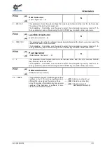
Pos: 330 /Anleitungen/Elektronik/FU und Starter/5. Parameter/Parameterauflistung (P000 ...)/P500-P599/Parameter P521 – Fangschaltung Auflösung @ 0\mod_1328092909572_388.docx @ 11364 @ @ 1
P521
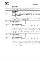
Fly. start resol.
(Flying start resolution)
S
P
0.02... 2.50 Hz
{ 0.05 }
Using this parameter, the flying start circuit search increment size can be adjusted. Values that
are too large affect accuracy and causes the FI to cut out with an overcurrent message. If the
values are too small, the search time is greatly extended.
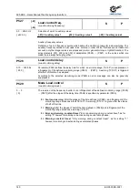
Pos: 331 /Anleitungen/Elektronik/FU und Starter/5. Parameter/Parameterauflistung (P000 ...)/P500-P599/Parameter P522 – Fangschaltung Offset @ 0\mod_1328093001838_388.docx @ 11387 @ @ 1
Summary of Contents for BU 0500
Page 1: ...EN BU 0500 SK 500E Users Manual for Frequency Inverters ...
Page 211: ......
Page 212: ...6075002 3021 ...


