5 Parameters
BU 0500 EN-1516
143
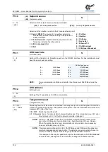
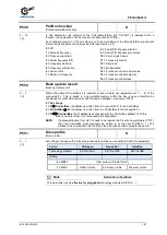
P537
Pulse disconnection
(Pulse disconnection)
S
10 ... 200 % / 201
{ 150 }
This function prevents rapid shutdown of the FI according to the load. With the pulse switch-off
enabled, the output current is limited to the set value. This limitation is implemented by brief
switching off of individual output stage transistors, the actual output frequency remains
unchanged.
10...200 % =
Limit value in relation to nominal FI current
201 =
The function is
so to speak
disabled,
the FI supplies the maximum
possible current. However, at the current limit the pulse switch-off can still be
active.
NOTE:
The value set here can be undershot by a smaller value in P536.
With smaller output frequencies (<4.5 Hz) or higher pulse frequencies (>6 kHz or
8 kHz, P504) the pulse switch-off can be undershot by the power reduction
(please see chapter 8.4 "Reduced output power").
NOTE:
If the pulse switch-off is disabled (P537=201) and a high pulse frequency is
selected in parameter P504, the FI automatically reduces the pulse frequency
when the power limit is reached. If the load on the FI is reduced again, the pulse
frequency increases back to the original value.
Pos: 345 /Anleitungen/Elektronik/FU und Starter/5. Parameter/Parameterauflistung (P000 ...)/P500-P599/Parameter P538 – Netzspannungsüberwachung @ 0\mod_1328093765682_388.docx @ 11686 @ @ 1
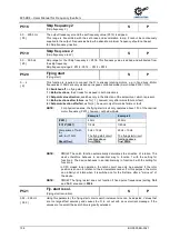
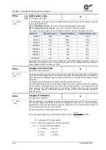
P538
Check input voltage
(Mains voltage monitoring)
S
0 ... 4
{ 3 }
For reliable operation of the inverter the power supply must meet a certain quality. If there is a
brief interruption of a phase or the voltage supply sinks below a particular limit value, the inverter
will output an error.
Under certain operating conditions, it may be necessary to suppress this error message. In this
case, the input monitoring can be modified.
0 = Switched off
: No monitoring of the supply voltage.
1 = Phase error
: an error message is only produced by phase errors.
2 = Mains voltage
: an error message is only produced by a low voltage.
3 = Phase err. + mains voltage
: A phase error or undervoltage produce an error message.
4 = DC supply
: The input voltage is fixed at 480V for the direct supply of direct current. Phase
error and low mains voltage monitoring are deactivated.
NOTE:
Operation with an impermissible mains voltage can destroy the frequency inverter!
With 1/3~230 V or 1~115 V devices, the phase error monitoring does not function!
Pos: 346 /Anleitungen/Elektronik/FU und Starter/5. Parameter/Parameterauflistung (P000 ...)/P500-P599/Parameter P539 – Ausgangsüberwachung @ 0\mod_1328093804307_388.docx @ 11709 @ @ 1
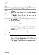
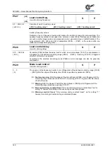
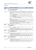
P539
Output monitoring
(Output monitoring)
S
P
0 ... 3
{ 0 }
This protective function monitors the output current at the U-V-W terminals and checks for
plausibility. In cases of error, the error message E016 is output.
0 = Disabled:
Monitoring is not active.
1 = Only motor phases:
The output current is measured and checked for symmetry. If an
imbalance is present, the FI switches off and outputs the error message E016.
2 = Only magnetisation:
At the moment the FI is switched on, the level of the excitation
current (field current) is checked. If insufficient excitation current is present, the FI switches
off with the error message E016. A motor brake is not released in this phase.
3 = Motor phase + Magnet:
Monitoring of the motor phases and magnetisation as in 1 and 2
are combined.
NOTE:
This function can be used as an additional protective function for lifting applications,
but is not permissible on its own as protection for persons.
Pos: 347 /Anleitungen/Elektronik/FU und Starter/5. Parameter/Parameterauflistung (P000 ...)/P500-P599/Parameter P540 – Modus Drehrichtung @ 0\mod_1328093845510_388.docx @ 11732 @ @ 1
Summary of Contents for BU 0500
Page 1: ...EN BU 0500 SK 500E Users Manual for Frequency Inverters ...
Page 211: ......
Page 212: ...6075002 3021 ...


