2
2
GENERAL SYSTEM DESCRIPTION
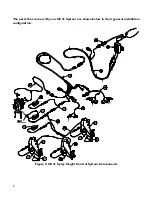
Figure 1
depicts the general system layout of the UC4+ Sprayer Boom Control System.
Figure 1: System Components and General Location
NOTICE:
Every effort has been made to ensure the
accuracy of the information contained in
this manual. All parts supplied are selected
specially to fit the sprayer to facilitate a
complete installation. However, NORAC
cannot guarantee all parts fit as intended
due to the variations of the sprayer by the
manufacturer.
Please read this manual
in its entirety before attempting
installation.
ATTENTION:
When installing the UC4+ Spray Height
Control system please be aware that at a
point in the installation your sprayer booms
will be inoperative until the installation is
complete.
Any installation procedure
requiring boom movement will need
to be done first.
Once the hydraulics
have been disconnected you must complete
the electrical installation before the booms
become operative.
Summary of Contents for UC4+ Apache 1010 2005+
Page 9: ...6 Figure 3 Hydraulic Plumbing Schematic ...
Page 27: ...24 5 ELECTRICAL REFERENCE CABLE DRAWINGS 5 1 ITEM C02 44668 CABLE SENSOR BRANCH ...
Page 28: ...25 5 2 ITEM C02B 44664 CABLE UC4 CAN NODE DUAL ...
Page 29: ...26 5 3 ITEM C03 44656D CABLE VALVE VARIABLE RATE DT ...
Page 30: ...27 5 4 ITEM C05 44674 CABLE UC4 SENSOR ROLL BIAS ...
Page 31: ...28 5 5 ITEM C10 44650 39 CABLE POWER GENERIC SELF PROPELLED L 100 2 54m ...
Page 32: ...29 5 6 ITEM C11 44651 03 CABLE VALVE EXTENSION GENERIC 365 9 27m ...
Page 33: ...30 5 7 ITEM C12 44658 18 CABLE UC4 VALVE AP2 MAIN ...
Page 34: ...31 5 8 ITEM C13 44658 17 CABLE UC4 SENSE AP2 ...
Page 35: ...32 5 9 ITEM C14 44658 99 CABLE UC4 INTERFACE POWER PIGTAIL FUSED ...


