13
4.4
MAIN LIFT SENSOR INSTALLATION
1.
Mount the bracket onto the lowest
frame member on the center section of
the sprayer. (
Figure 14
and
Figure
15)
.
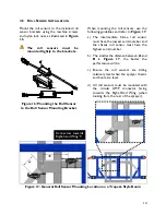
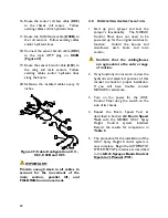
Figure 13: Main Lift Sensor Bracket
Mounting
The General Mounting Rules for
Low Profile Brackets and the
General Mounting Rules for
UC4+ Ultrasonic Sensors, from
the previous section, must be
followed.
2.
Mount the sensor into the bracket.
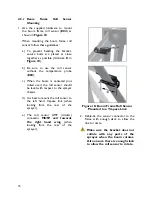
Figure 14: Main Lift Sensor Bracket
Mounting Position (Top View)
Figure 15: Main Lift Sensor Bracket
Mounting Position (Side View)
Summary of Contents for UC4+ Apache 1010 2005+
Page 9: ...6 Figure 3 Hydraulic Plumbing Schematic ...
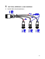
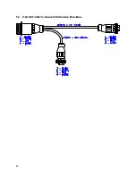
Page 27: ...24 5 ELECTRICAL REFERENCE CABLE DRAWINGS 5 1 ITEM C02 44668 CABLE SENSOR BRANCH ...
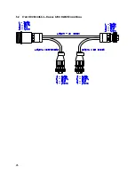
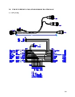
Page 28: ...25 5 2 ITEM C02B 44664 CABLE UC4 CAN NODE DUAL ...
Page 29: ...26 5 3 ITEM C03 44656D CABLE VALVE VARIABLE RATE DT ...
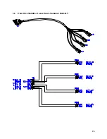
Page 30: ...27 5 4 ITEM C05 44674 CABLE UC4 SENSOR ROLL BIAS ...
Page 31: ...28 5 5 ITEM C10 44650 39 CABLE POWER GENERIC SELF PROPELLED L 100 2 54m ...
Page 32: ...29 5 6 ITEM C11 44651 03 CABLE VALVE EXTENSION GENERIC 365 9 27m ...
Page 33: ...30 5 7 ITEM C12 44658 18 CABLE UC4 VALVE AP2 MAIN ...
Page 34: ...31 5 8 ITEM C13 44658 17 CABLE UC4 SENSE AP2 ...
Page 35: ...32 5 9 ITEM C14 44658 99 CABLE UC4 INTERFACE POWER PIGTAIL FUSED ...


