background image


41 

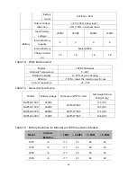
NOTE Battery times are approximate and vary depending on the load 
configuration and battery charge. 

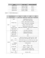
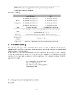
Table 17.


Battery 

                        Internal Batteries 

EBPs 

Battery 

Configuration 

1000 VA: 24 Vdc (2,12V, 9 Ah)   

1500 VA: 36 Vdc (3,12V, 9 Ah) 

2000 VA: 48 Vdc (4,12V, 9 Ah)                     

3000 VA: 72 Vdc (6,12V, 9 Ah) 

  24 Vdc (2 x 2,12V, 9 Ah)   

  36 Vdc (2 x 3,12V, 9 Ah) 

  48 Vdc (2 x 4,12V, 9 Ah)   

  72 Vdc (2 x 6,12V, 9 Ah) 

Fuses 

(2) 30A/250Vdc fuses 

(4) 30A/250Vdc fuses per EBP 

Type 

Sealed, maintenance-free, valve-regulated, lead-acid, with minimum 3-year 

float service life at 25°C (77°F) 

Monitoring 

Advanced monitoring for earlier failure detection and warning 

Recharge Time 

(to 90%) 

8 hours to 90% 

Battery Port 

External six-pole Anderson connector on UPS for connection to EBP 

8


Troubleshooting 

The  following  messages  are  the  information  that  users  would  find  on  UPS  when  it  meets  some 
problems. Users can judge if the fault is caused by external factors and know how to deal with it by 
making full use of the information. 
Fault indicator on, indicates that the UPS has detected some faults. Buzzer beeps, indicates that UPS 
need to be paid attention to, if beeps for a long time, it means that there is something wrong with the 
machine.  If  you  need  help,  contact  our  service  department,  the  following  messages  should  be 
provided for analysis: 
 

◆UPS MODEL NO. and SERIAL NO. 
◆Date of fault happened 
◆Detailed description of the problem   
◆Alarms and codes 


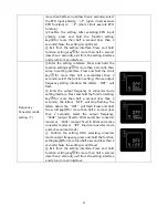
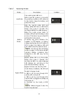
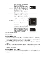
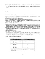
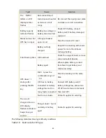
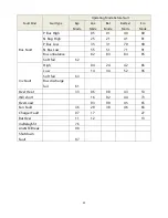
The following table describes typical alarm conditions. 

Table 18.


Summary of Contents for NUPS23-1000

Page 1: ...1 NUPS23 1KVA to 3KVA 120 240VAC Rack Tower Convertible User Guide...

Page 2: ...may cause harmful interference to radio communications However there is no guarantee that interference will not occur in a particular installation If this equipment does cause harmful interference to...

Page 3: ...symbol indicates that you should not discard the UPS or the UPS batteries in the trash This product contains sealed lead acid batteries and must be disposed of properly For more information contact y...

Page 4: ...4 Table of Contents 1 Introduction 5 2 Safety Warnings 6 3 Installation 7 4 Operation 18 5 Communication 31 6 UPS Maintenance 35 7 Specifications 38 8 Troubleshooting 41...

Page 5: ...o 0 8 Three segment charging mode to increase battery service life optimize recharge time Selectable High Efficiency mode of operation Cold start function to startup the UPS without utility Standard c...

Page 6: ...d with branch circuit overcurrent protection in accordance with the National Electrical Code NEC ANSI NFPA 70 Output overcurrent protection and disconnect switch must be provided by others To comply w...

Page 7: ...n 15 days to your service representative Unpacking the Cabinet CAUTION Unpacking the cabinet in a low temperature environment may cause condensation to occur in and on the cabinet Do not install the c...

Page 8: ...are included for each cabinet Left rail assembly Left rail Rear rail 3 M5_8 pan head screws Right rail assembly Right rail Rear rail 3 M5_8 pan head screws Rail hardware kit 8 M5 butterfly nuts 2 rea...

Page 9: ...bly to the front of the rack with one M5 12 pan head screw and one M5 cage nut Using two M5 cage nuts and two M5 12 pan head screws to fix the rail assembly to the rear of the rack FIG 4 Fixing the Ra...

Page 10: ...ptional cabinets FIG 6 Securing the Front of the Cabinet 13 Continue to the following section Rackmount Wiring Installation Rackmount Wiring Installation This section explains Installing the UPS inclu...

Page 11: ...ount of arcing may occur when connecting the internal batteries This is normal and will not harm personnel Connect the cables quickly and firmly FIG 8 Connecting the UPS Internal Batteries 3 If you ar...

Page 12: ...d bonding screw See Rear Covers for the location of the ground bonding screw for each model 7 If an emergency power off disconnect switch is required by local codes see Remote Emergency Power off REPO...

Page 13: ...This is normal and will not harm personnel Insert the EBP cable into the UPS battery connector quickly and firmly 5 Plug the EBP cable s into the battery connector s as shown in FIG 12 Up to four EBPs...

Page 14: ...near the left side of the EBP cabinet Repeat for each additional EBP It is the same with the installation of the front cover Refer to UPS installation 8 Verify that all wires connected between the UPS...

Page 15: ...lation two plastic base brackets flatten it after interlocking Interlock as follows FIG 13 Plastic base installation If an EBP is needed to be placed in the middle the assembly of plastic base is simi...

Page 16: ...E F FIG 14 Increase EBP plastic base 2 The installation between UPS and EBPs FIG 15 The installation for UPS and battery box 1 Install the base and place the RT UPS on the base one by one as Fig 15 sh...

Page 17: ...l turn on and off sequentially 8 Check the UPS front cover display for active alarms or notices Resolve any active alarms before continuing See Troubleshooting If the indicator is on do not proceed un...

Page 18: ...tion about the UPS itself load status measurements and settings see FIG 16 FIG 16 Control Cover Table 1 Indicator Descriptions Indicator Description Red On The UPS has an active alarm or fault Yellow...

Page 19: ...on orderly Press and hold this key for more than 2 seconds Circularly and orderly display the items every 2 seconds when press and hold the key for some time again it will turn to output status Functi...

Page 20: ...ce every four seconds 4 Battery disconnect warning Bypass mode Once every four seconds Affirm if the battery switch is closed Inverting mode inverting mode Once every four seconds Affirm if the batter...

Page 21: ...or maintenance when you can t deal with it by yourself _indicator lights for a long time _indicator flashes _the status of indicator depends on other conditions Display Functions As the default or aft...

Page 22: ...the dynamic fan blades rotating when the fan works abnormally the icon will keep on flashing with the warning Charger status graphics section Display the status of the charger When charger works norma...

Page 23: ...rature Display the temperature of the inverter in the UPS As the following graphics show the temperature of the inverter is 37 Input Display the voltage and frequency of the input As the following gra...

Page 24: ...ress and hold the function setting key for more than half a second less than 2 seconds Now the ECO setting function is completed and the ON or OFF below the ECO will light without flash If you choose...

Page 25: ...range To set the minus range in the same way After the minus range is confirmed Long press function setting key for more than 2 seconds to exit setting menu Output voltage setting 3 Enter the setting...

Page 26: ...key for more than half a second less than 2 seconds select the numerical value in accordance with the real connected battery strings Confirm the battery strings setting interface After selecting nume...

Page 27: ...t the function setting choose output frequency setting interface the letters OPF will flash Enter the output frequency of converter mode setting interface Press and hold the function setting key for m...

Page 28: ...attery voltage reaches low limit UPS will turn off to protect the battery UPS will auto restart when the mains recover NOTE The back up time of battery mode is subject to the load and EBP numbers Batt...

Page 29: ...Code Standby Mode When UPS is plugged into line and not turn on the UPS will work in standby mode to charge the battery No indicator displays on this mode UPS Turn on and Turn off Start up operation T...

Page 30: ...for more than 1 second the LEDs light and go out circularly and orderly The UPS comes to self test mode and tests its status It will exit automatically after finishing testing and the LED indication...

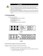
Page 31: ...city You had better not use the ECO mode when the quality of the input AC mains is not good 5 Communication This section describes the Communication ports RS 232 and USB Connectivity cards Emergency P...

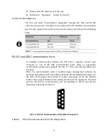
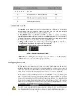
Page 32: ...nd a computer connect your computer to one of the UPS communication ports using an appropriate communication cable not supplied See FIG 17 18 for the communication port locations When the communicatio...

Page 33: ...Before installing the connectivity card please remove the clip from the bay Refer to the user s manual of the appropriate cards Emergency Power off EPO is used to shut down the UPS from a distance Th...

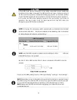
Page 34: ...f the Buildings Part 4 Protection for Safety Chapter 46 Isolation and Switching EPO Connections Wire Function Terminal Wire Size Rating Suggested Wire Size EPO L1 4 0 32 mm2 12 22 AWG 0 82 mm2 18 AWG...

Page 35: ...tended Battery Packs EBPs Test new batteries Recycle used batteries or UPS UPS and Battery Care For the best preventive maintenance keep the area around the UPS clean and dust free If the atmosphere i...

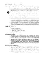
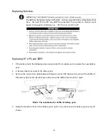
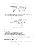
Page 36: ...ff Replacing RT UPS and EBPS 1 If the battery fault the following steps are provided for modular unit to replace the new battery pack 2 2 Remove the front cover of the battery box 3 Remove the connect...

Page 37: ...start up combination button 3 Press the battery test combination button to activate the battery test The UPS starts a battery test if the batteries are fully charged the UPS is in Normal mode with no...

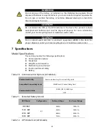
Page 38: ...al or electronic equipment WEEE in the trash For proper disposal contact your local recycling reuse or hazardous waste center 7 Specifications Model Specifications This section provides the following...

Page 39: ...60 Hz 0 5Hz auto sensing 46Hz 54Hz 0 5Hz 50HZ or 56Hz 64Hz 0 5Hz 60HZ Power factor 0 98 Current harmonic 10 100 linear load output Output style Single phase and ground Rated voltage 100 108 110 115 12...

Page 40: ...midityu humidity 0 95 non condensing Altitude 1500m lower the rated power for use Store temperature 25 55C Table 15 Mechanical Specification Model Battery voltage Dimension W D H mm Net weight Gross W...

Page 41: ...ours to 90 Battery Port External six pole Anderson connector on UPS for connection to EBP 8 Troubleshooting The following messages are the information that users would find on UPS when it meets some p...

Page 42: ...S overload Check the usage of loads remove some redundant devices Battery aged When replace battery contact franchiser to get battery and relative assembly UPS doesn t startup after pressing the ON ke...

Page 43: ...1 41 81 P Bus Low 35 31 70 90 N Bus Low 55 51 71 91 Bus unbalance 82 83 84 85 Soft fail 62 Inv Fault High 04 24 42 86 Low 14 34 52 96 Soft fail 63 Bus discharge fail 61 Over Heat 33 06 08 43 53 INV sh...

Reviews: