Nisca PR5300 User Manual Download Page 38


34 


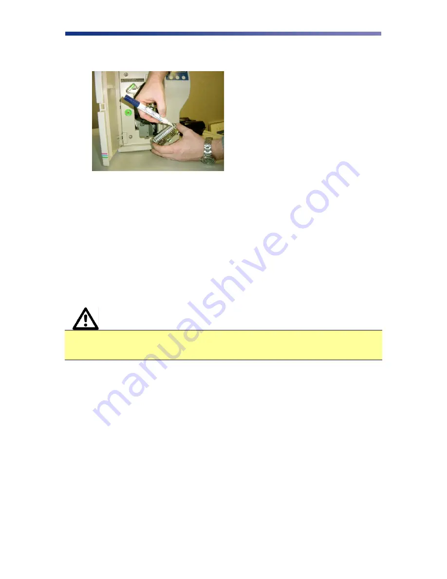
6.  Using a print head cleaning pen, firmly wipe back and forth across the surface of the print 

head. 


7.  Once the print head is completely dry, reinstall the print head in reverse order. 

Updating the Firmware 

The firmware is internal software that controls the operation of the hardware.  Occasionally, new 
firmware versions are released which have updated and/or new features.  New firmware updates 
can be downloaded from the Nisca website at www.teamnisca.com and loaded into your printer 
using the “Download Utility” program.  No physical replacement or repair of any parts is 
required, so this process is simple.  Download the appropriate file(s) based on your interface and 
operating system.  If you do not have Internet access and are unable to access these files, contact 
your authorized reseller for assistance. 


Caution


IMPORTANT! 

It is critical that all printers, 

including

 the Nisca PR5300 be 

temporarily removed from LPT1 for the firmware utility to function.  One 
recommendation is to change all printer drivers from LPT1 to LPT2.   

Refer to the following steps to update your firmware: 

1.  Download and install the Firmware Update Utility from www.teamnisca.com. 

Summary of Contents for PR5300

Page 1: ...Lane Somerset NJ 08873 Copyright 2004 Kanematsu USA All rights reserved TEAMNisca and the TEAMNisca logo are a registered trademark of Kanematsu USA Inc Microsoft and Windows are U S trademarks of Mi...

Page 2: ......

Page 3: ...g Cards 13 Card Size Adjustment 14 Turning On the Printer 15 Printer Driver Installation 15 Installing the Windows 2000 XP Print Driver Parallel 15 Installing the Windows 2000 XP Print Driver SCSI 18...

Page 4: ...ubleshooting Suggestions 40 Where to Get Additional Help 40 Block Diagram 41 Appendix A Printer specifications 42 Appendix B Printer Configuration 44 Appendix C User Mode Menu Map 46 Appendix D Parts...

Page 5: ...on compatibility This printer produces cards ideal for driver s licenses printing bureaus access control badges and standard corporate identification About This User s Guide This User s Guide contains...

Page 6: ...printer Do not place any heavy objects on the printer Use only a power source indicated in the electrical requirements section Do not place the printer on an unstable surface or near a radiator or a...

Page 7: ...must be connected to a grounded electrical power supply and properly protected against electrical surges and grounding faults Physical Requirements The PR5300 requires a sturdy platform that can acco...

Page 8: ...Release Button Button that allows the front access panel to open C Card Output Stacker Used to store printed cards D Card Input Feeder Used to load blank cards for printing E LCD Display Display s th...

Page 9: ...there is a direct short or excessive heat B Interface Port Connection SCSI II Parallel USB C Options Connector Port The printer supports the attachment of a optional card lamination module D Power Re...

Page 10: ...for menu selections F Clear Button Normal User Used for clearing or resetting errors It is also used to stop continuous printing In some cases it is used to set values G EXE Button Normal User Not us...

Page 11: ...inter 1 Place the shipping carton on a firm level surface While unpacking inspect the carton to ensure no damage occurred during shipping 2 Remove the printer and carton components from the packing bo...

Page 12: ...print head packing material from the ribbon cartridge Loading The Ink Ribbon Caution IMPORTANT To prevent damage to the print head you must press the Ribbon Change button BEFORE removing the ribbon c...

Page 13: ...side of the ribbon cartridge 3 Locate the empty ribbon bobbin packaged with the printer accessories and place on the take up side of the ribbon cartridge 4 Remove the tape and pull the released ribbo...

Page 14: ...access panel Connecting The Printer This section describes how to connect the printer to a power source and to a PC that runs the printer driver Depending on the model you purchased it can be connect...

Page 15: ...e EXE button to return to the Ready to Print display 6 Depending on where your printer exists on the SCSI chain will determine the selection of the termination switch If the printer is in the middle o...

Page 16: ...llel port and snap the fastening clips into place 3 Connect the other side of the cable to the parallel connector on the back of the computer 4 Insert the power cord into the power receptacle on the r...

Page 17: ...s printing The printer is factory configured to feed and print standard size CR 80 at 30 mil To adjust the card thickness see the next section To load cards following these steps 1 Lift the card feede...

Page 18: ...that vary from the standard size it is necessary to make a simple adjustment to the printer To adjust the card size follow these steps 1 Open the card feeder door and remove cards 2 Loosen the two phi...

Page 19: ...stall the driver under Windows 2000 and Windows XP you must have Administrator privileges The PR5300 printer comes with different printer drivers for the Microsoft operating systems The printer driver...

Page 20: ...he parallel port set to ECP enhanced capability port If the message is Your computer is configured to support ECP printing continue on with the installation If you receive any other message you should...

Page 21: ...7 Verify the components to install 8 Click Next 9 The setup application will now install and configure the printer driver 10 Click Finish to complete the printer driver installation 11 After installa...

Page 22: ...sert the Nisca installation CD in your computer s CD drive 2 On the Start menu click Run 3 Type d setup where d is the letter assigned to your CD drive 4 Click OK The printer driver Setup starts and g...

Page 23: ...agreement and click Yes if you accept the terms of the license agreement If you decline you cannot install the driver 3 Enter your customer information 4 Click Next 5 Enter the registration informatio...

Page 24: ...s not detected verify the cable connections and proper setting of the termination switch on the back of the printer If the PR5300 printer is the last device on the SCSI bus the termination switch must...

Page 25: ...to restart my computer now for the updates to take effect Printing a Test Card A sample application is included with the installation of the printer driver To print a sample card refer to the followin...

Page 26: ...22 4 The sample application will load 5 Select File Print 6 Select the Nisca printer you would like to use to print the sample 7 Click OK to print the sample card...

Page 27: ...ftware application Settings that control the printing and personalization of the card are found under Printing Preferences These settings include To open the printer driver Printing Preferences please...

Page 28: ...O in a ribbon for example YMCKO Thermal Overlaminate A thicker protective layer applied by the attached Heat Roller Unit The optional Heat Roller Unit can apply a thin film roll that can sometimes con...

Page 29: ...nter any information desired in the User 1 and User 2 fields You may also change font attributes and print location using the options in the Attributes group About Tab The about tab displays copyright...

Page 30: ...Refer to the printer s LCD display for information Also refer to Chapter 5 for troubleshooting To erase output data from the printer s memory press and hold the Clear button for 3 seconds The LCD wil...

Page 31: ...minimum cleaning requirement guideline CLEANING SCHEDULE CLEANING TOOL Takeup Roller 10 000 prints Alcohol Swab Input Rollers 2 000 prints Alcohol Swab Card Flip Turn Transport Rollers 10 000 prints A...

Page 32: ...k cards 4 Remove the protective paper backing from both sides of the cleaning card 5 Insert the Cleaning Card into the feed gate until the card stops 6 Press the EXE button to begin the cleaning proce...

Page 33: ...takeup roller 2 Use an alcohol swab to wipe the roller clean Use your fingertips to move the roller back and forth while cleaning 3 After the roller has been cleaned and is completely dry reload the...

Page 34: ...Clean the rollers with an alcohol cotton swab in the direction pictured 4 Once the dust and debris is cleaned from the rollers place the assembly module back into the printer Push it in until it hit s...

Page 35: ...n knob and use an alcohol swab to clean the rubber and white plastic rollers 4 After cleaning the flip turn transport rollers proceed to cleaning the print unit rollers in the next section Cleaning th...

Page 36: ...ity To clean the print head you will need a print head cleaning pen available from your authorized reseller Caution IMPORTANT The print head may be hot Turn off the power and let the print head cool b...

Page 37: ...release button Lift the green retaining lever and remove the ribbon cartridge 4 Using a phillips screwdriver remove the retaining bracket 5 Press the metal latch to release the print head and gently s...

Page 38: ...r printer using the Download Utility program No physical replacement or repair of any parts is required so this process is simple Download the appropriate file s based on your interface and operating...

Page 39: ...o the folder in which you saved the update file select it and click Open 5 A dialog box will ask you to confirm executing the update Click Yes This will begin the firmware update process that will onl...

Page 40: ...nterpreting General LCD Messages LCD SCREEN MESSAGE PROBABLE CAUSE ACTION Initializing The printer is performing an internal test before use Wait for the Ready to Print message Ready to Print The prin...

Page 41: ...ibbon type specified in the printer settings Enter User Mode on the printer and change the settings in the Ribbon Type sub menu to match the ribbon type installed in the printer i e YMCK YMCKO YMCKOK...

Page 42: ...rn unit Use the green dial to advance the card in a position easier for removal If this error occurs again clean the rollers in the flip turn unit Card Jam Print Area A card is jammed between the flip...

Page 43: ...gth Print head is dirty Clean the print head If problem persists you may need to replace the print head Avoid dirty cards because they can damage the print head over time Random bands or streaks Print...

Page 44: ...rt to ECP You must change the parallel port mode through your system BIOS or setup screen The system BIOS is generally entered by holding down a specific character while your computer is booting up Th...

Page 45: ...41 PR5300 Block Diagram Flip Turn Feeder Print Unit Encoder...

Page 46: ...s Output feeder capacity Up to 100 cards Image memory 8MB with parallel processing four memory modes Display LCD 16 character 2 line display shows printer status and diagnostic prompts Print Speed1 YM...

Page 47: ...10 66 W x 13 03 D 421mm x 271mm x 331mm Weight 28 6 lbs 13 kg Operating Temperature 65 to 80o F 18 to 27o C Power source 100 240 Volts AC 50 60Hz auto switching Agency listing UL CE FCC Driver compat...

Page 48: ...4 A P P E N D I X B Printer Configuration ITEM NAME DESCRIPTION A Card Feeder The cards automatically feed off the bottom of the stack The slot is 1 5 times the thickness of the card to A B C D E F G...

Page 49: ...it and is pressed against the surface of the card E Print Head The component of the printer that actually does the printing This component is fragile and must not be bumped or touched with anything ot...

Page 50: ...llow Adjustment Printer Ribbon Ribbon Selection Image Setup Black Print Mode High Speed High Quality Magenta Adjustment Return to Normal Mode Error Buzzer On Off Image Data Print Cyan Adjustment Retur...

Page 51: ...Main Program Setup Data Reset Finish Return to Normal Mode Encoder Type Lo Co High Co Head Code Return to Normal Mode Encode First On Off Encoder Unit Return to Parent Encode Mode Card side selection...

Page 52: ...nce several parts should be replaced on a periodic basis The following table outlines these parts and the suggested replacement time frame PART NUMBER OF PRINTS TOOLS NEEDED Input Roller Every 40 000...

Page 53: ...assembly module back into the printer Push it in until it hit s the stops Close the front access panel Replacing the Print Head Caution IMPORTANT The print head may be hot Be sure the printer has ade...

Page 54: ...release button Lift the green retaining lever and remove the ribbon cartridge 4 Using a phillips screwdriver remove the retaining bracket 5 Press the metal latch to release the print head and gently s...

Page 55: ...rint head and reinstall in reverse order 8 Insert the floppy disk that came with the print head This data must be loaded to the print head before using the printer 9 Use the firmware update utility as...

Reviews: