


·
52
·
No.
Dia .x
Width
.
1
CB5-75
26x20.2x2
Red
copper
6
Low pressure pipe of gear pump,
release oil pipe of lift.
2
CB5-75
23x17.2x2
Red
copper
4
High pressure oil pipe of gear pump,
head of oil intake component.
3
CB5-75
22.5x16.5x2
Red
copper
4
Screw plug of oil release pipe, screw
plug of output hole, oil cylinder
safety valve.
B. Frame Oil Seal.
No.
Standard
Open type,
Bore Dia. x Exradius x Width
Qty.
Purposes.
1
JB2600-80
PD80 X105X 12
4
Drive shaft gland
2
JB2600-80
PD 55X75X12
4
Brake
3
JB2600-80
SD45X65X10
2
PTO shaft, main pin, pulley.
4
HG4-692-67
35X56X12
2
Primary shaft front bearing cap.
5
GB98771.1 -88
60X85X8
4
Front hub.
6
BY130-3401010
32X44X10
1
Steering gear.
C. O-type Seal Ring.
N
o.
Drawing No.
External (inner) Dia.
X
Cross Dia.
Qty.
Purposes.
1
GB1235-76
90X5.7
1
Bearing cap of II shaft ,transmission.
2
GB1235-76
18X2.4
1
Lift oil cylinder, spring shackle seat of
φ
85 bore
3
GB1235-76
68X3.1
2
Gear
pump housing
4
GB3452.1-82
40X5.3
2
Front wheel main pin.
5
Q/ZB248-77
YxD85(for hole)
4
Piston
φ
85, cylinder.
6
GB3452.1-82
34.5x3.55
2
Swing shaft, front axle
7
GB1235-76
32x3.1
1
Reverse gear shaft.
4
Front and rear cap, gear pump.
8
GB1235-76
31x3.5
1
Transmission coupling.
9
GB1235-76
26x2.4
3
Main control valve bush.
10
GB1235-76
25x2.4
1
Low pressure connector and oil pump.
11
GB1235-76
22x2.4
1
Front cap of valve
1
Oil-returning valve plug.
1
Upper cover, distributor.
2
Pin shaft, rear axle.
2
Oil-returning valve bush.
2
Cam shaft, brake.
12
GB1235-76
20x2.4
1
Control plate, lift.
1
Oil pump and high pressure connector.
2
Fork shaft, PTO shaft
Summary of Contents for Benye 35 Series
Page 1: ......
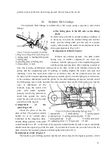
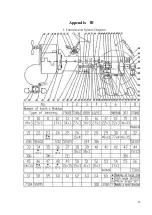
Page 5: ... 4 Appendix Ⅲ 51 Ⅰ Sketch of Transmission System 51 Ⅱ Diagram of Linkage Hitch 52 ...
Page 41: ... 40 ...
Page 43: ... 42 rotating timer steering indicating lights a charging alarm indicating device etc ...
Page 59: ... 58 Appendix Ⅲ ...
Page 60: ... 59 II Dimensional Sketch of linkage System END ...
Page 61: ... 60 ...