


·
32
·
bevel gear of the II-shaft should be kept within the range of 0.98--1.47 N.m.(0.1--0.15 Kg.fm).
IV. Transfer Case.
The transfer case of BY354 and 404 four-wheel-drive tractors, is fixed below the carrier case,
consists of a gear shaft connecting shaft , PTI and PTO shafts, gears, a transmission shaft, etc.,
and is used to take out or cut off the power from the front drive axle and to keep the front and
rear drive wheels synchronously rotating. During its operation and maintenance, the transfer case
is generally unnecessary to be adjusted, while the following items should be noticed.
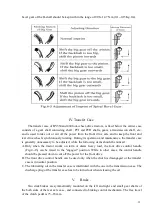
A. Only when the tractor works on farm or draws heavy load, the font drive control handle
(Fig.4--13) can be raised to the "engaged" position. While in other cases, the control handle
should be pressed down to cut off the power for the front drive.
B. The front drive control handle can be used only when the clutch is disengaged or the transfer
case is in neutral position.
C. The lubricating oil in the transfer case is interlinked with the one in the transmission case. The
discharge plug of the transfer case has to be turned out when releasing the oil.
V.
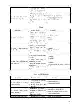
Brake .
Two disk brakes are symmetrically mounted on the left and right end small gear shafts of
the both sides of the rear axle case , and connected to braking control mechanism. The free travel
of the clutch pedal is 75--85 mm.
Summary of Contents for Benye 35 Series
Page 1: ......
Page 5: ... 4 Appendix Ⅲ 51 Ⅰ Sketch of Transmission System 51 Ⅱ Diagram of Linkage Hitch 52 ...
Page 41: ... 40 ...
Page 43: ... 42 rotating timer steering indicating lights a charging alarm indicating device etc ...
Page 59: ... 58 Appendix Ⅲ ...
Page 60: ... 59 II Dimensional Sketch of linkage System END ...
Page 61: ... 60 ...