


·
21
·
down for complete separation, and then the control handle should be lifted up or pressed
down before the power is supplied or cut off.
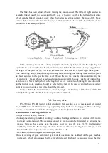
G.Use of Differential Lock.
When one side of the rear wheels of the tractor slips and sanks, the differential lock handle
should be pushed to the right , and the two semi-shaft gears and the block of the differential are
rigidly locked together to make
the
two
rear wheels moving at the same time
and passing
through sliding field. Afterwards, the differential handle is released immediately and the
differential mechanism automatically backs to its original position. The differential handle is
used only when the tractor stops or runs at low speeds and is strictly forbidden to be used in the
case of sharp-turning or running at high speeds.
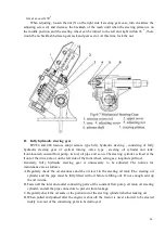
H. Stop of the Tractor and Shut-Off of the Engine
a. Reduce the foot throttle to slow down the speed of the tractor(Fig.4--11)
b. Step down the clutch pedal and then depress the brake pedal when the tractor stops, put the
main gearshift lever to neutral position.(Fig.4--9and 4--10).
c. Release the clutch and brake pedals and let the engine run in idle speed.
Notice; On emergency stopping, follow No.5.2.
d. Keep the engine running at lower speed for a period of time to decrease slowly the
temperature of the oil and the water. Strictly forbid to stop the engine running at high
temperature.
e. Push the hand throttle to the off position.
f. Draw out the shut-off rod to stop fuel supplying to the injection pump, and the engine shuts
off immediately. Push the rod back to the fuel supplying position (See Fig.4--1).
g. Take the key out of the preheating switch.(Fig.4--7 and 4--1)
h. To protect the machine body from cracking due to freezing of the cooling water in Winter,
unscrew the two water draining valves and the cap of water tank to release
the water
completely.
i. Turn off oil tank cock in case of long time stopping of the tractor.
Summary of Contents for Benye 35 Series
Page 1: ......
Page 5: ... 4 Appendix Ⅲ 51 Ⅰ Sketch of Transmission System 51 Ⅱ Diagram of Linkage Hitch 52 ...
Page 41: ... 40 ...
Page 43: ... 42 rotating timer steering indicating lights a charging alarm indicating device etc ...
Page 59: ... 58 Appendix Ⅲ ...
Page 60: ... 59 II Dimensional Sketch of linkage System END ...
Page 61: ... 60 ...