


·
25
·
b. Take off the sealing cover and its paper gasket from the oil pump and fasten them.
c. Fix the pulley assy. on the PTO shaft.
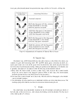
d. Push the auxiliary gearshift lever to the neutral position, the main lever in the positions of
Gear I and II (to have the bearing of the I-shaft completely lubricated), the output drive shaft
handle in the engaged position, the PTO shaft handle in low speed positions, and then keep
the pulley running at low speeds.
e. After driving the tractor to a suitable place, shut off the engine and push the PTO shaft handle
to neutral position.
f. Fix the stationary machine, have the pulley in correct position and keep the belt with suitable
tension. If necessary, move the machine or the tractor.
g. Pull the belt by hand to check the installation, and then fix the machine and the tractor.
h. Start the engine to drive the belt. At the
beginning, keep the engine running at low
speed and then check the work of the engine
with running at higher speeds.
i.
While a mechanical group works normally, its
required running speed can be obtained by
adjusting the hand throttle. But it is not
suitable to reduce the running speed too much
because the output is reduced with decreasing
of the running speed. Notice: When the engine
runs , it is always to step down the clutch
pedal .
Summary of Contents for Benye 35 Series
Page 1: ......
Page 5: ... 4 Appendix Ⅲ 51 Ⅰ Sketch of Transmission System 51 Ⅱ Diagram of Linkage Hitch 52 ...
Page 41: ... 40 ...
Page 43: ... 42 rotating timer steering indicating lights a charging alarm indicating device etc ...
Page 59: ... 58 Appendix Ⅲ ...
Page 60: ... 59 II Dimensional Sketch of linkage System END ...
Page 61: ... 60 ...