


19
Eng
lis
h (
EN
)
110002490
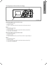
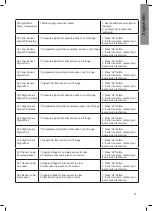
Loctite 577 is used at the factory to seal the thread,
but packing yarn/packing tape can also be used.
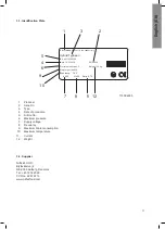
9.7. Components
9.7.1. Pumps/motor
Pumps/motor are maintenance free.
9.7.2. Control system
Maintenance free
If defective: Call a service technician
9.7.3. Flow switch
Maintenance-free.
If defective, replace the flow switch.
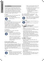
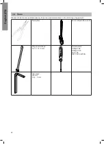
30°
30°
110002491
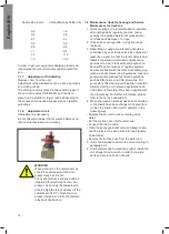
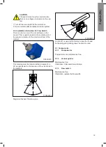
CAUTION
The system must only be serviced when
there is no voltage or pressure on the sys-
tem
1. Turn off the main switch at the control box
2. Open a water outlet to depressurise the system
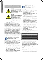
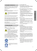
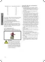
9.6. Installation Instruction for Flow Switch
There is a dot on one of the nut surfaces on the
sensor. This is used to position the contact point of
the sensor in relation to the direction of flow of the
medium.
This marking must be located within an angle of +/-
30° perpendicular to the direction of flow, as shown in
the example.
Flow
30°
30°
Mark
Diagram of sensor fitted in a pipe.
110000973
Summary of Contents for Hybrid Typhoon
Page 1: ...Hybrid Typhoon Directions for use Gebrauchsanweisung Mode d emploi Instrucciones de uso...
Page 80: ......
Page 86: ...8 2 4 5 6 1 3 7 110004550 Hybrid Typhoon...
Page 88: ...Hybrid Typhoon 1 3 2 4 5 110004554...
Page 90: ...17198_30 1 2 3 Hybrid Typhoon...
Page 92: ...Hybrid Typhoon 110004551 1 2...
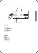
Page 94: ...Hybrid Typhoon 1 2 3 4 9 8 7 6 5 10 7 8 12 11 13 110004548...
Page 96: ...Hybrid Typhoon 110004552 1 2 3...
Page 98: ...Installation 658 1435 1011 1107 110004599...
Page 100: ...El diagram 110004767E...
Page 101: ...El diagram...
Page 102: ...El diagram...
Page 103: ...110004775D El diagram...
Page 104: ...El diagram...
Page 105: ...El diagram...
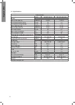
Page 107: ...Pump curve 25 bar 50 Hz...
Page 109: ...Layout Hybrid MU...
Page 111: ......