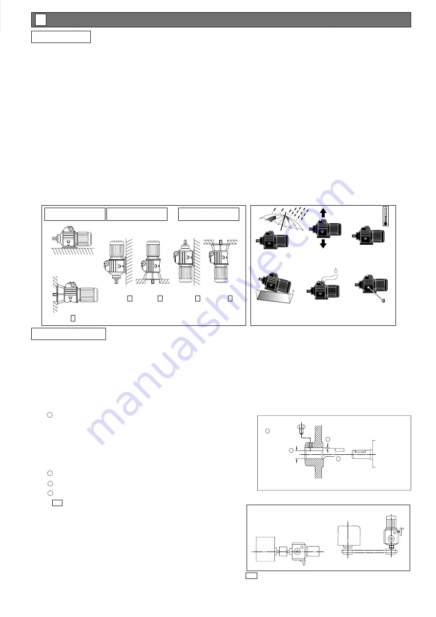
background image

5


NRXMK Y

Base type

NRXMK Z

Base type

NRXMK V

Flange type

NRXMK I

Flange type

NRXMK  X  Flange type

c

b

a

d

2. When connecting the product, do not apply impact force and/or excessive thrust load on the output shaft


 (use tapping hole on the output shaft for 11K to 18K).

  a 

 Since the output shaft diameter dimension tolerance of the speed drive has been 

set to h6 for 200B to 7500, and m6 for 11K to 18K, set the hole tolerance of the 

coupling,  pulley,  chain  sprocket,  and  gear,  which  are  to  be  mounted,  to  H7  for 

200B to 7500, and F7 for 11K to 18K. Then, push the output shaft into the hole 

by tapping with a wooden or plastic hammer.   Pushing the shaft by hitting it hard 

could result in damage to bearings and/or the inside of the speed drive.

   b Chamfer the hole mouth by approximately 1 mm.

   c Make clearance of 0.1 mm to 0.2 mm for the key head.

   d Hold and secure the key head using a set bolt.

3.Ensure centering before connection.

■  For  connection  with  a  coupling,  properly  align  the  speed  drive  shaft  with 

the mated machine shaft.  

■ For connection with pulley, chain sprocket, and gear, etc., properly make 

the speed drive shaft parallel with the mated machine shaft, determine the 

correct center line, and fit precisely.

Note : Make the effective diameter of the coupling, pulley, chain sprocket, and gear, etc. at least 

five  times  the  output  (input)  shaft  diameter  of  the  speed  drive.  Be  careful  not  to  allow 

impact, vibration, and/or excessive thrust load from the machine to apply to the shaft ends. 

(For information about allowable shaft weight, refer to the catalog).

1. Allow a sufficient margin when setting the rotating speed and torque.

■  When driving the mated machine at the maximum speed, connect the speed drive so that it also operates at the maximum rotation.

■  For machines of which torque increases at the lower speed (such as those with constant horsepower characteristics), set the maximum torque to be 

within the rated torque of the speed drive.

1

NRXMK Base type

30cm

Maintain an ambient 
temperature between 
0ºC and 40ºC

Make it easy to add 
and drain oil

Install horizontally on a 
vibration-free bench

Keep from getting wet

Provide  sufficient 

clearance

Make the oil gauge 

easily visible

10cm

1-1 Installation

1-2 Connections

1. Avoid installing the product in a place directly exposed to rain or water.

■  Consult us in advance if you use the product outdoors, or in a place exposed to dust or water.

2.Install the product in an area with an ambient temperature of between 0ºC and 40ºC.

■  If you plan to use the product beyond the above mentioned temperature range (at higher or lower temperature), be sure to consult us.

3.Securely fix the product using bolts on a solid installation bench that is not prone to vibration.

■  Install the horizontal type horizontally, the vertical type (with downward output shaft) and inverted type (with upward output shaft) 

vertically. Failure to follow this could result in malfunction due to poor lubrication.

For inclined installation, consult us.

4. Install the product in a way that provides easy access for inspection and maintenance.

■  To make it easy to add and drain lubricating oil, install the product at a level of approximately 10 cm from the floor by securing a top 

clearance of approximately 30 cm.

■  When installed the product into machines, place it so that the oil level can be checked externally, and lubricating oil can be easily replaced 

using pipes.

[ Output shaft direction and installation direction ]           [ Installation conditions ]

Note : The output shaft rotation direction for the speed drive equipped with a 

Coronet speed reducer (N11, 17, 29, 35, 47, 59, 71 types) is the same as that 
of the input shaft.

 Installation

Horizontal type

 (with horizontal output shaft) 

Vertical type 

(with downward output shaft) 

Inverted type 

(with upward output shaft)

Set bolt

Adjustable 
speed drive

Output shaft

Coupling
Pulley
Chain sprocket
Gear

Mated machine

Mated machine

Coupling

Belt, chain, gear

Speed drive

Speed drive

Summary of Contents for RINDCODE NRX Series

Page 1: ...ecautions Operating Precautions Storing Precautions Installation Operation Special Lubricating Oil Periodical Inspection Troubleshooting Disassembly Reassembly 1 2 4 5 6 8 11 11 12 NRX Series Instruct...

Page 2: ...carefully read these safety precautions and follow them for proper use WARNING Indicates a potentially hazardous situation that may result in serious injury if you incorrectly handle this product CAU...

Page 3: ...ate position Note that the output speed might change if a load changes greatly Output Speed When using product continuously use it in the middle and high speed areas which secures high efficiency If a...

Page 4: ...ck to ensure that there is no oil leakage Periodical inspection every three months Check to ensure that pulleys sprockets and speed drive mounting bolts are not loose Check to ensure that there are no...

Page 5: ...lied oil cooler pump unit Water cooled system Operate with special oil and drain oil at shipping The air breather has been sealed Eliminate water from pipes completely dry and seal the cooling water o...

Page 6: ...set the maximum torque to be within the rated torque of the speed drive 1 NRXMK Base type 30cm Maintain an ambient temperature between 0 C and 40 C Make it easy to add and drain oil Install horizonta...

Page 7: ...et Oil outlet Vertical type Rubber hose Rubber hose Air cooled system Horizontal type Oil filter Air cooled oil cooler OUT Oil outlet Pump unit IN Oil inlet Oil inlet Oil inlet Oil outlet Oil outlet V...

Page 8: ...r pump unit 1 Never turn the speed change handle when operation stops when the motor is not running 2 Be careful not to overload 3 The surface temperature of the speed drive housing under normal opera...

Page 9: ...he type of lubricating oil differs between the speed change and speed reduction sections In the event that different types of oil are used sufficient performance may not be attained or extension of th...

Page 10: ...ug position in the center of the speed reduction section indicates the proper oil level Remove the upper lubrication plug and level plug and fill with oil until oil flows out of the level plug SC O N...

Page 11: ...5 0 15 15 18 18K C11 21 H 5 0 4 6 15 7 C29 43 L 5 0 15 15 18 NRX Inscribed planetary reducer L N C 200B to 7500 200B to 7500 Model 11K 15K 18K Model 11K 15K 18K Oil filling port in the speed reduction...

Page 12: ...rease load to the specified level Pressure contact of the driving surface may be defective Adjust the pressure contact condition The driving surface may have been worn Replace the ring and cone with n...

Page 13: ...within the range of values in the table below If backlash is too large or small remove the bearing cover and adjust to the normal value by increasing or decreasing the shim 0 1 mm to 0 2 mm thick 3 R...

Page 14: ...ing to 1 to 3 add a shim 0 2 mm thick Model Clearance of the cam disc 3700 to 18K Adjust clearance to 0 to 0 1 mm and add a shim 0 1 mm to 0 15 mm thick 0 05 mm to 0 1 mm thick when applying pressure...

Page 15: ...t force ER flange Cover NRX 200B to 2200 N Adjust by cam retainer backlash NRX 3700 to 7500 N Adjust by clearance between the cam disc and input cam Model Cam retainer backlash 200B 400B 750 1500 1 to...

Page 16: ...204 51305 1500 6206ZZ 6206 51206 51405 2200 6207ZZ 6207 51207 51407 6008 3700 6208ZZ 6307 51307 51408 6010 5500 7500 6210ZZ 6308 51308 51410 6011 6210LLU 6011LLU Oil seal name number list Output shaft...

Page 17: ...XK For the speed change section refer to page 15 Bearing name number list Oil seal name number list D Thrust bearing E F G Ball bearing ZZ metal seal type LLU contact rubber seal type Input disc D Inp...

Page 18: ...E F G H Ball bearing ZZ metal seal type LLU contact rubber seal type B D Thrust bearing Output shaft A Output shaft B Output shaft C Input disc D Input disc H Motor shaft E Motor shaft F 11K 15K 6312...

Page 19: ...203 3 6206ZZ 3700 4T 30210 6012 4T 30206 6002 4 6204 3 6207ZZ 5500 7500 4T 30211 6013 4T 30207 6002 4 6305 3 6208ZZ Oil seal name number list Output shaft 2R Input shaft 2S 200B 400B D25408 S20358 Oil...

Page 20: ...low speed side Bearing housing on the low speed side Primary pinion Primary gear Secondary pinion Secondary gear Output shaft Key for the primary pinion Key for the primary gear Key for the secondary...

Page 21: ...brackets The number of pieces without bracket indication is one Bearing name number list Cone retainer Cone Output cam Cam retainer Cam disc Packing on the output shaft side Base Output shaft Output s...

Page 22: ...ove the bolt from the carrier pin and release the output shaft 6 Remove the wheel bush and eccentric roller bearing on the output shaft side 7 Remove the spacer 8 Remove the wheel bush and eccentric r...

Page 23: ...speed section Cover Gland Snap ring shaft for bearing 7 Low speed shaft with Note 3 Worn or damaged oil seals collars and or packing etc could result in oil leakage Be sure to replace them with new o...

Page 24: ...e f e r t o p a g e 1 5 O u t p u t s h a f t s e c t i o n S p e e d c h a n g e s e c t i o n I n p u t s h a f t s e c t i o n F o r d e t a i l s o n t h e o u t p u t s h a f t s e c t i o n r e...

Page 25: ......

Page 26: ......

Page 27: ......

Page 28: ...Address 1 Terada Kohtari Nagaokakyo city Kyoto 617 0833 Japan Phone 81 75 958 1298...

Reviews: