background image

7

Operate the oil cooler pump unit according to the following procedures.

■ Be sure to provide a separate power supply to the pump unit from the speed drive motor.

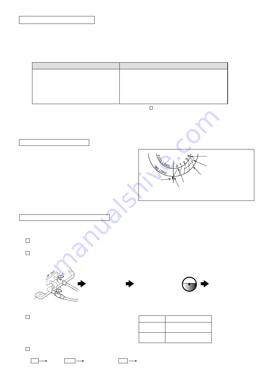
 1  Before operation, be sure to open the oil inlet (outlet) valves (two positions) of the speed drive.

* Operating the pump unit with those valves closed could result in malfunction of the pump unit.


2  Turn the power switch of the oil cooler pump unit ON, and confirm that there is no problem with oil feeding conditions between the speed drive 

main unit and pump unit, then turn the power switch of the speed drive ON.

 3  Confirm the rotation direction of the cooler pump unit motor.

1. Perform wiring so that the motor rotates in a counter-clockwise 

direction when viewed from the motor fan side.

2. For the indication position of the rotation direction, refer to the table 

on the right.


4  Inspection and cleaning of the oil filter


・ The filter clogging condition will be indicated by 

“color” 

in the detector inside the filter on top of the oil cooler pump unit, depending on the degree of use.

For NRXMK-18K (including models equipped with the reducer)

Blue

Yellow 

White

Normal

 Clean the element

 Danger (clean or replace the element)

Model

Indication position

RXCA-01

RXCW-01

Indicated on the motor

RXCW-01-1
RXCW-01-2

Indicated on the pump unit

Turn the power switch of 
the oil cooler pump unit ON

Open the oil inlet (outlet) valves of the speed drive

Turn the power switch 

of the speed drive ON

Confirm that the oil cooler pump 
unit has been filled with oil

Confirm that oil has been supplied at the specified 
level of the oil gauge in the speed drive

Base

2-4 Operation of the oil cooler pump unit

1. 

Never turn the speed change handle when operation stops 

(when the motor is not running).  

2. Be careful not to overload.
3.The surface temperature of the speed drive housing under normal operation can reach up to approximately 50ºC higher than 

the ambient temperature.

4.If the following events occur, stop operation immediately, and inspect the unit. Take any necessary procedures.


* For more details on the above symptoms and possible causes of problems, refer to “ 5  Troubleshooting” on page 11.

5.Switch between forward and reverse rotation after checking that the motor (input) shaft has stopped operation completely.


Instantaneous switching between forward and reverse rotation could result in malfunction.


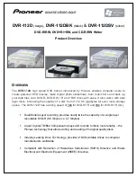
For NRX, the rotation will not change as long as the load 
does not change.

If a load changes greatly, however, the rotation speed will 
change even at the same graduation point.

1. Read the graduation on the dial depending on the load.

2. Note that the rotation speed will change if a load changes greatly.

 (We recommend using the automatic control when high accuracy 

is desired).

(*1) Rotation speed for the type without the reducer

2-2 Precautions during operation

2-3 Dial graduation and load

Symptoms

Possible causes

・ The temperature suddenly increases.
・ An abnormal, loud noise is suddenly generated.
・ The rotation speed suddenly becomes unstable.
・ Other abnormal events are found.

・ The unit has been overloaded
・ Lubricating oil has been excessively or insufficiently used, 

or has deteriorated. Or, a different type of lubricating oil has 
been used.

・ Bearings and/or drive surfaces have been damaged
・ Improper connecting conditions with the mated machine, etc.

Dial position at 100% load

Dail position at medium load

Mating mark

Dial position at no load

0 rpm at this point with 100% load

20  rpm  (when  1800  rpm  is  input)  at 
this point with no load (*1)

Summary of Contents for RINDCODE NRX Series

Page 1: ...ecautions Operating Precautions Storing Precautions Installation Operation Special Lubricating Oil Periodical Inspection Troubleshooting Disassembly Reassembly 1 2 4 5 6 8 11 11 12 NRX Series Instruct...

Page 2: ...carefully read these safety precautions and follow them for proper use WARNING Indicates a potentially hazardous situation that may result in serious injury if you incorrectly handle this product CAU...

Page 3: ...ate position Note that the output speed might change if a load changes greatly Output Speed When using product continuously use it in the middle and high speed areas which secures high efficiency If a...

Page 4: ...ck to ensure that there is no oil leakage Periodical inspection every three months Check to ensure that pulleys sprockets and speed drive mounting bolts are not loose Check to ensure that there are no...

Page 5: ...lied oil cooler pump unit Water cooled system Operate with special oil and drain oil at shipping The air breather has been sealed Eliminate water from pipes completely dry and seal the cooling water o...

Page 6: ...set the maximum torque to be within the rated torque of the speed drive 1 NRXMK Base type 30cm Maintain an ambient temperature between 0 C and 40 C Make it easy to add and drain oil Install horizonta...

Page 7: ...et Oil outlet Vertical type Rubber hose Rubber hose Air cooled system Horizontal type Oil filter Air cooled oil cooler OUT Oil outlet Pump unit IN Oil inlet Oil inlet Oil inlet Oil outlet Oil outlet V...

Page 8: ...r pump unit 1 Never turn the speed change handle when operation stops when the motor is not running 2 Be careful not to overload 3 The surface temperature of the speed drive housing under normal opera...

Page 9: ...he type of lubricating oil differs between the speed change and speed reduction sections In the event that different types of oil are used sufficient performance may not be attained or extension of th...

Page 10: ...ug position in the center of the speed reduction section indicates the proper oil level Remove the upper lubrication plug and level plug and fill with oil until oil flows out of the level plug SC O N...

Page 11: ...5 0 15 15 18 18K C11 21 H 5 0 4 6 15 7 C29 43 L 5 0 15 15 18 NRX Inscribed planetary reducer L N C 200B to 7500 200B to 7500 Model 11K 15K 18K Model 11K 15K 18K Oil filling port in the speed reduction...

Page 12: ...rease load to the specified level Pressure contact of the driving surface may be defective Adjust the pressure contact condition The driving surface may have been worn Replace the ring and cone with n...

Page 13: ...within the range of values in the table below If backlash is too large or small remove the bearing cover and adjust to the normal value by increasing or decreasing the shim 0 1 mm to 0 2 mm thick 3 R...

Page 14: ...ing to 1 to 3 add a shim 0 2 mm thick Model Clearance of the cam disc 3700 to 18K Adjust clearance to 0 to 0 1 mm and add a shim 0 1 mm to 0 15 mm thick 0 05 mm to 0 1 mm thick when applying pressure...

Page 15: ...t force ER flange Cover NRX 200B to 2200 N Adjust by cam retainer backlash NRX 3700 to 7500 N Adjust by clearance between the cam disc and input cam Model Cam retainer backlash 200B 400B 750 1500 1 to...

Page 16: ...204 51305 1500 6206ZZ 6206 51206 51405 2200 6207ZZ 6207 51207 51407 6008 3700 6208ZZ 6307 51307 51408 6010 5500 7500 6210ZZ 6308 51308 51410 6011 6210LLU 6011LLU Oil seal name number list Output shaft...

Page 17: ...XK For the speed change section refer to page 15 Bearing name number list Oil seal name number list D Thrust bearing E F G Ball bearing ZZ metal seal type LLU contact rubber seal type Input disc D Inp...

Page 18: ...E F G H Ball bearing ZZ metal seal type LLU contact rubber seal type B D Thrust bearing Output shaft A Output shaft B Output shaft C Input disc D Input disc H Motor shaft E Motor shaft F 11K 15K 6312...

Page 19: ...203 3 6206ZZ 3700 4T 30210 6012 4T 30206 6002 4 6204 3 6207ZZ 5500 7500 4T 30211 6013 4T 30207 6002 4 6305 3 6208ZZ Oil seal name number list Output shaft 2R Input shaft 2S 200B 400B D25408 S20358 Oil...

Page 20: ...low speed side Bearing housing on the low speed side Primary pinion Primary gear Secondary pinion Secondary gear Output shaft Key for the primary pinion Key for the primary gear Key for the secondary...

Page 21: ...brackets The number of pieces without bracket indication is one Bearing name number list Cone retainer Cone Output cam Cam retainer Cam disc Packing on the output shaft side Base Output shaft Output s...

Page 22: ...ove the bolt from the carrier pin and release the output shaft 6 Remove the wheel bush and eccentric roller bearing on the output shaft side 7 Remove the spacer 8 Remove the wheel bush and eccentric r...

Page 23: ...speed section Cover Gland Snap ring shaft for bearing 7 Low speed shaft with Note 3 Worn or damaged oil seals collars and or packing etc could result in oil leakage Be sure to replace them with new o...

Page 24: ...e f e r t o p a g e 1 5 O u t p u t s h a f t s e c t i o n S p e e d c h a n g e s e c t i o n I n p u t s h a f t s e c t i o n F o r d e t a i l s o n t h e o u t p u t s h a f t s e c t i o n r e...

Page 25: ......

Page 26: ......

Page 27: ......

Page 28: ...Address 1 Terada Kohtari Nagaokakyo city Kyoto 617 0833 Japan Phone 81 75 958 1298...

Reviews: