8 – English
EN
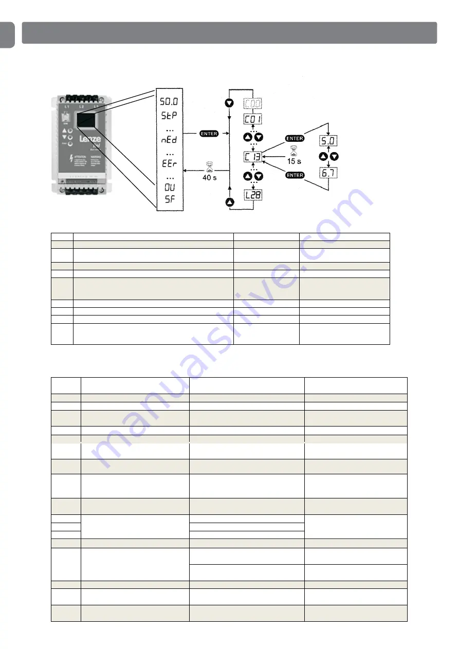
PARAMETER SETTINGS ON THE INVERTER
It is possible to set a number of parameters on the inverter
Error/
status
Description
Cause
Remedy
50_0
Current output frequency
Regular operation
OFF
Stop (outputs U,V,W blocked)
LOW signal on terminal 28
Set terminal 28 on HIGH
STP
Output frequency = 0 Hz
Outputs U,V,W blocked
Quickstop via digital input
Disable Quickstop
CL
The current limit was reached
Adjustable overload
Automatic
LU
Undervoltage in the intermediate circuit
Mains voltage too low
Check the mains voltage
dEC
Overvoltage in the intermediate circuit
during the process (warning)
Process time very short
Automatic if overvoltage duration < 1 s,
otherwise error DU
nED
No access to the code
Modifiable only if the regulator is set on OFF
or inh
Set terminal 28 on LOW
rC
The remote control is enabled
An attempt to use buttons on the front of
the regulator was detected
The buttons on the front are disabled if
the remote control is enabled
Contact our
Ad
Error A/D inverter
Assistance service
cF
The data in EPM are invalid
The data are not valid for the regulator
Use EPM with valid data, upload the
factory settings
CF
Data error
9F
The OEM data are invalid
F1
EPM error
EPM is missing or is damaged
Disable and replace the EPM
CF9
Digital input not uniquely
assigned
E1...E3 have been assigned the same digital
signals
Every digital signal can be used only one
time
Only "UP" or only "DOWN" used
Assign the missing digital signal to a
second terminal
dF
Error braking chopper
The braking resistors are overheated
Increase the process time
EEr
External fault
A digital input configured with "TRIP-‐Set" is
enabled
Eliminate the external fault
FC 5
F2....F0
Internal fault
Contact our Assistance Service
Code
Name
Adjustment range
Pre-‐set
C10
Minimum output frequency
15-‐20 Hz
15 Hz
C11
Maximum output frequency
50-‐150 Hz
with 0.75kW -‐ 10 Hz
from 1.5kW to 5.5kw 80Hz
C12
Speed increase time
1.0-‐1.8 s
1.0 s
C13
Performance time
0.7-‐1.2 s
0.7 s
C16
Booster
adjust in small steps max. 2% in one step only
A setting too high or too low jeopardises door operation
0-‐40%
10%
C17
Frequency threshold (Qmin)
13.5-‐18.5 Hz
13.5 Hz
C01
Speed increase time (2)
0.4-‐0.8 s
0.4 s
C02
Performance time (2)
0.2-‐0.5 s
0.2 s
C08
Relay output configuration
0-‐8
0 with operating current brake
2 with spring force brake
7 inverter brake relay not used


