Newman 4VAL Operating And Maintenance Manual Download Page 12

4VAL Operating & Maintenance Manual    Version 1.1    © Newman Labelling Systems Ltd                                    Page 12 of 56  

Documented  training  with  certificates  for  all  attendees  along  with  course 
documentation  is  increasingly  being  requested  and  Newman  is  able  to  quote  and 
provide this service. Please contact Newman for further information. 
 
 
2.3 INSTALLATION 


Prior  to  starting  Installation  it  is  important  to  fully  understand  the  following 
instructions. Unpack the machine very carefully to avoid damage and make sure that 
all small items and boxes are retained before discarding the packaging. Screw in the 
four  adjustable  feet  (or  castors),  move  the  machine  into  position,  set  the  conveyor 
height and level machine by adjusting the feet. 
 
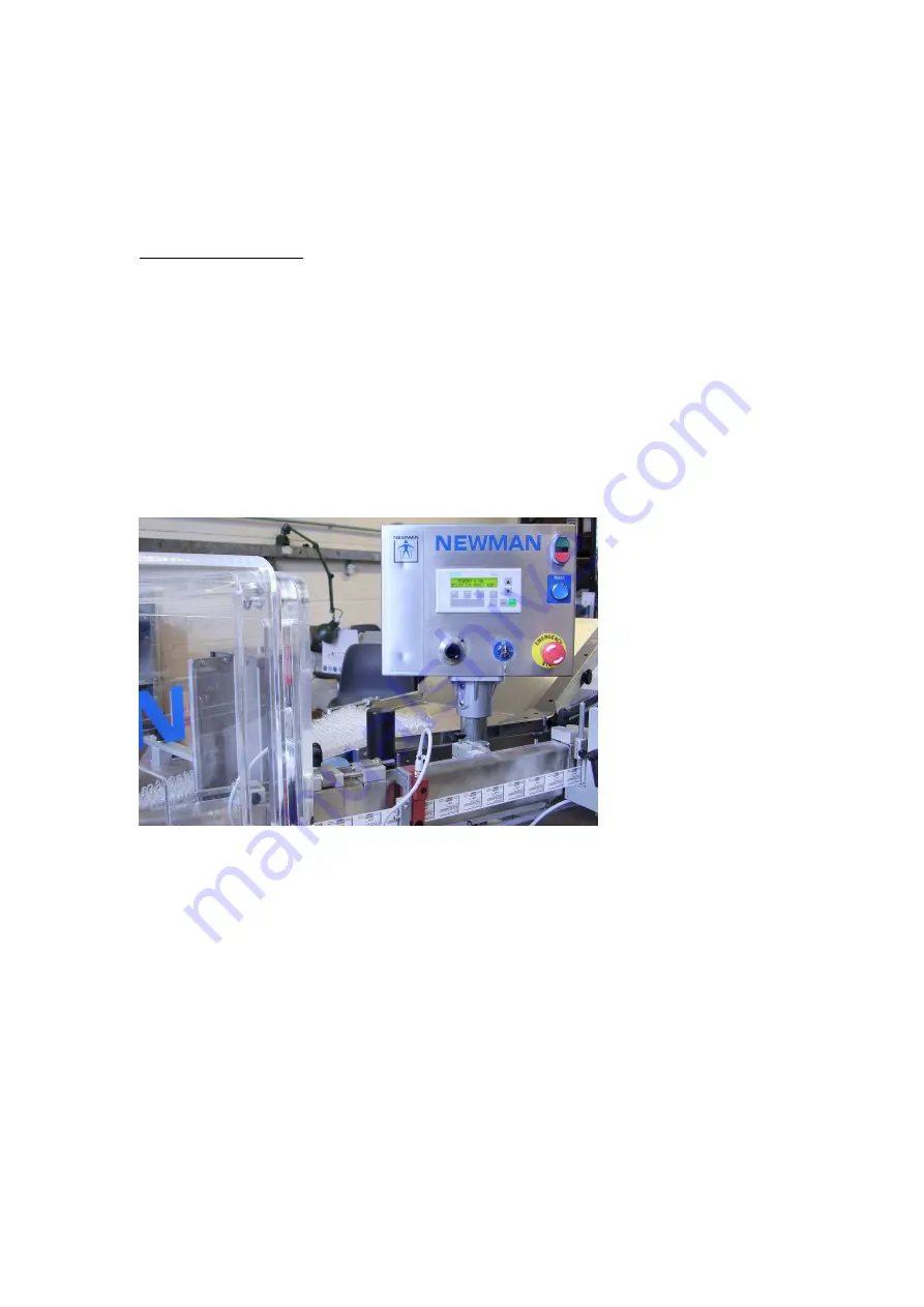
The  Operator  Panel  has  been  lowered  to  approximately  guard  level  for  transport 
purposes  as  shown  in  photo  below.  This  needs  to  be  raised  to  a  suitable  height  for 
operation. Ensure that one person supports the box before another person releases the 
clamp to raise the box.  


Operator panel lowered for shipment 
 
Reassemble  the  coder  (if  fitted)  to  the  machine  and  connect  the  pneumatic  and 
electrical services. The coder is usually secured onto the label arm mounting bracket 
with 4 off M6 socket head screws. 
 
Check that  your electrical supply details correspond with those on the machine plate 
and machine electrical drawings. Ensure that a suitably qualified person connects the 
supply  to  the  isolator.  If  your  supply  uses  an  earth  leakage  circuit  breaker  (ELCB)  / 
residual current device (RCD) it is recommended to be 100mA minimum trip rating.   
 
The  machine  is  supplied  with  all  guards  necessary  for  safe  operation.  If  any 
modifications are made for any reason, care should be taken to ensure that the overall 
safety is not impaired. 
 

Summary of Contents for 4VAL

Page 1: ...and design rights in the drawings contained therein This manual is provided in confidence solely for the purpose of enabling the operation installation repair and maintenance of equipment provided by...

Page 2: ...3 2 ON OFF BUTTONS 15 3 3 EMERGENCY STOP 15 3 4 RESET BUTTON 15 3 5 MACHINE SPEED 15 3 6 FAULT MESSAGE INDICATION 15 3 7 DESCRIPTION OF FAULTS 16 3 7 1 EMERGENCY STOP 16 3 7 2 GUARD OPEN 16 3 7 3 LAB...

Page 3: ...NHIBITOR 37 4 7 OVERPRINT SENSOR 37 4 8 PRODUCT SENSOR 38 4 9 REJECT SENSOR 40 4 10 MISSING LABEL SENSOR UV 40 4 11 MISSING LABEL DETECTION 41 4 12 ULTRASONIC LABEL RUNOUT SENSOR 42 4 13 STRIPPER PLAT...

Page 4: ...ch number expiry date or other variable information can be added to the labels as they pass from the reel to the labelling station Containers to be labelled are fed on a bulk conveyor where they are r...

Page 5: ...29915a Components Container Diameter 10 50 mm Label Height 12 70 mm Minimum Label Width 25 mm Min base to bottom of label 1 mm Maximum reel diameter 300 mm Min core diameter 45 mm Alternative core Dia...

Page 6: ...Standard Thermal Transfer Coder Option Option Option Double Label Feed Inhibitor Option Standard Standard Ultrasonic Label Sensors Option Option Option Label Runout Sensor Option Option Standard Missi...

Page 7: ...ES AND SERVICE OFFICE ENGLAND NEWMAN LABELLING SYSTEMS LTD QUEENS ROAD BARNET EN5 4DL TELEPHONE 44 0 20 8440 0044 FAX 44 0 20 8449 2890 E MAIL spares newman co uk Attn Rosemarie Owens USA SPARES CAN B...

Page 8: ...tandards have been used EN292 parts 1 and 2 1991 Safety of Machinery Basic concepts general principles for design EN294 1992 Safety of Machinery Safety distances to prevent danger zones being reached...

Page 9: ...eader 5 Coder 6 Overprint detector 7 Waste web take up 8 Label sensor 1 9 Label feed rollers 10 Label sensor 2 11 Guard rear door 12 Stripper plate 13 Applicator drum 14 Electrical cabinet 15 Outfeed...

Page 10: ...are where practicable covered by fixed guards These must be maintained in the best condition to ensure no hazard is introduced All Fixed Guards i e screwed or bolted panels and covers should be secur...

Page 11: ...Pressure Compressed air is used on the machine for operation of coder If fitted No risk is present provided the user s supply line is securely installed Dust As paper labels and webbing release a qua...

Page 12: ...d level for transport purposes as shown in photo below This needs to be raised to a suitable height for operation Ensure that one person supports the box before another person releases the clamp to ra...

Page 13: ...fed and applied The container continues to be rolled by the drum to ensure overall adhesion The label arm is fitted with label control sensor s and optional overprinting overprint verification and bar...

Page 14: ...pads Although two different PLCs are used the functions modes switches and alarm messages are the same for both versions Operator Panel Controls 3 1 MODE KEY SWITCH The control system operates in two...

Page 15: ...un at approximately 10 of maximum speed 3 6 FAULT MESSAGE INDICATION A machine fault will first stop the machine then give a fault message indication on the display at the operator panel in either RUN...

Page 16: ...rgency stop immediately removes power from the main motor and it will not be certain that label application is complete or that the missing label sensor has correctly identified label presence as the...

Page 17: ...one and either re thread through the machine or splice onto the old labels Acknowledge the alarm message Siemens enter Allen Bradley reset Press the machine start button 3 7 4 PRINTER FAULT CAUSE a H...

Page 18: ...led container from applicator drum Acknowledge the alarm message Siemens enter Allen Bradley reset Press the machine start button Monitor label application after restart 3 7 6 OVERPRINT FAULT CAUSE A...

Page 19: ...n Monitor the bar code reader on start up NB Barcode detection can be by barcode scanner or by vision system The alarm message is the same for both 3 7 8 MOTOR DRIVE FAULT CAUSE a A fault on the main...

Page 20: ...ared and the fault message acknowledged by pressing the ENTER button before the machine can be restarted Refer to Machine Operation General section for detailed description and corrective actions for...

Page 21: ...d Page 21 of 56 3A 2 MODES The control system operates in either RUN or SET UP mode and these are accessed via the key switch The following diagram shows the screens selectable in each mode for all op...

Page 22: ...ng alarm messages and restarting the machine Viewing the counters Test firing labels F4 button Counters Current counter values can be viewed by using the UP or DOWN arrow keys on the keypad to scroll...

Page 23: ...still function correctly providing it is correctly set but the control system will not act upon the signals the machine will not stop and a fault message will not be displayed Scroll through screens w...

Page 24: ...4VAL Operating Maintenance Manual Version 1 1 Newman Labelling Systems Ltd Page 24 of 56 Overprint Inhibit Screen UV Sensor Inhibit Screen Barcode Inhibit Screen Product Sensor Inhibit Screen...

Page 25: ...first stop the machine then give a fault message indication on the display at the operator panel in either RUN or SETUP mode The fault must be cleared and the fault message acknowledged by pressing th...

Page 26: ...d Page 26 of 56 3B 2 MODES The control system operates in either RUN or SET UP mode and these are accessed via the key switch The following diagram shows the screens selectable in each mode for all op...

Page 27: ...hine speed Clearing alarm messages and restarting the machine Viewing the counters Test firing labels F4 button Counters Current counter values can be viewed by using the UP or DOWN arrow keys on the...

Page 28: ...still function correctly providing it is correctly set but the control system will not act upon the signals the machine will not stop and a fault message will not be displayed Scroll through screens w...

Page 29: ...4VAL Operating Maintenance Manual Version 1 1 Newman Labelling Systems Ltd Page 29 of 56 Overprint Inhibit Screen UV Sensor Inhibit Screen Barcode Inhibit Screen Product Sensor Inhibit Screen...

Page 30: ...nge over is undertaken The following procedure assumes that the machine is to be run on the delivery set up but it is recommended that the sections describing the relevant controls be read prior to ma...

Page 31: ...ners is not uniform then re adjust the presser pad in or out by turning the TRACK GUIDES hexagonal adjuster Peel labels from the backing material for about 0 5 metres Place label reel on feed disc and...

Page 32: ...nsor settings Further operations of the F4 jog button may be necessary to bring a label to the application point and provide sufficient waste web to be fed into the take up spool Adjust label sensor s...

Page 33: ...ERS Adjust setting to obtain appropriate grip on the container by adjusting the gap between the applicator drum and presser pad using the adjuster on the front of the machine 4 4 LABEL FEED Before fee...

Page 34: ...S Photoelectric label sensors used for paper labels The procedure for setting is Set Label Sensor 1 before Label Sensor 2 Place the web without labels into the slot in the sensor so that the label web...

Page 35: ...lackened tightened to avoid twisting the electrical connection wire Otherwise for sensor operation the connection must be in place Position the sensor probe on the gap between the labels and adjust th...

Page 36: ...rt the web with labels Press the teach button on the sensor green LED flashes Pull the web through under slight tension so that 5 to 10 labels pass through the sensor Press the green button again gree...

Page 37: ...ob detector is fitted to the labelling machine to verify the presence of an overprint on the label The sensor is essentially a contrast detector that is typically used to detect black overprint on a w...

Page 38: ...n BKGD Move the label so the light spot is now on the background and press the BKGD pushbutton the green LED blinks once The green LED should now be permanently ON If the green LED flashes slowly the...

Page 39: ...applicator drum by hand so the sensor fibre optic head is only seeing the applicator drum background and not a container Press the SET button ONCE After approximately three 3 seconds the set LED shoul...

Page 40: ...missing label fault if no label presence signal was received The setting is the same as the product sensor above 4 10 MISSING LABEL SENSOR UV A luminescence sensor UV Sensor is fitted to the labellin...

Page 41: ...ow focus field of view Hence quite a long signal will be received from the missing label sensor and quite a short signal from the reject sensor The timing of these signals must be such that the UV sen...

Page 42: ...ON NOTE The Ultrasonic sensor used for label runout has been modified by the addition of a small piece of thin plastic bonded into the sensing gap to enable function as a runout sensor This sensor is...

Page 43: ...cessary Any sideways tilt of the stripper plate is corrected by adjusting the labelling head table laterally as described in earlier section The angle Y which the side of the stripper plate makes with...

Page 44: ...ce is levelled using a spirit level Re tighten the bolts after this setting is complete The front edge of the stripper plate is set at 90 degrees to the conveyor by slackening the stripper plate secur...

Page 45: ...s is done by tilting the arm as described in c but only turning the adjusting screw F about turn to tilt the arm in the desired direction Re align the stripper plate at 90 degrees to conveyor as in d...

Page 46: ...ed from presser pad Remove presser pad 2 fixing bolts Remove UV sensor where fitted from presser pad Select and fit new presser pad refit sensors to presser pad Change infeed guides or tray fitments f...

Page 47: ...uired speed run containers through machine to test labelling Once label application is acceptable enable missing label detection and check function Ensure position of printer is correct and enable ove...

Page 48: ...d rollers by hand If the web is cut by the serrations then the gap needs to be increased If the web can easily be pulled through slipping then the gap needs to be decreased Eccentric Shaft Adjustment...

Page 49: ...rd serrated label feed rollers as shown in the previous Operating Maintenance manual Subject to machine testing and with certain web materials the stainless steel knurled and rubber rollers shown belo...

Page 50: ...IS CORRECT W EB REW IND CLUTCH IS SLIPPING CODER DW ELL IS NOT TOO LONG LABEL SENSORS SET CORRECTLY LABEL APPLICATION OK CHECK ALL ITEMS ABOVE IN LABEL FEED OK PRODUCT SENSOR SET CORRECTLY GRIP ON CON...

Page 51: ...EAKER CB1 CHECK MAINS FILTER OUTPUT VOLTAGE FLT1 CHECK VOLTAGE AT TRANFORMER IF FITTED CHECK MAIN FUSE F1 NO YES NO 24V POWER SUPPLY OK CHECK MAIN FUSE F1 CHECK SECONDARY SIDE OF PSU FOR 24 VDC YES PO...

Page 52: ...osits on the label feed rollers If contaminated proceed thus a Remove three securing screws at the top of the guard and then carefully ease the guard upwards taking care not to damage the rollers b Re...

Page 53: ...by pressing the water drain plunger at the bottom of the bottle Clean conveyor belts stripper plate presser and presser pad removing any dirt and sticky deposits Clean the lens face of all the sensor...

Page 54: ...t the holes in the fan cowl are clear and that no dirt or other obstructions are present in the cowl or along the body extrusions Ensure that all fixing screws are firm and tight Check that the connec...

Page 55: ...TED ROLLER 1 10276 SLAT BELT 1FT 5 14978 FILTER PAD 120 X 120 3 20447 RUBBER 3 X 155 X 355 BLACK 1 23127 CLUTCH BRAKE 1 23420 PANEL FAN 24V DC 6 23432 3AMP QUICK BLOW FUSE 2 26134 OPTO RELAY 1 26182 C...

Page 56: ...ons 14 Keyswitch 14 L Label Count 22 27 Label Height 5 Label jog 23 28 Label Runout 15 17 Label sensor 34 Label Width 5 Label Winding 9 Layout Drawing 9 30 Luminescence sensor 40 M Maximum reel diamet...

Reviews: