5
5. There is excessive condensation on windows in the winter; or
6. A ventilation system is installed in the house.
If these or other indications that infiltration air is inadequate, additional combustion air should be provided from
the outdoors.
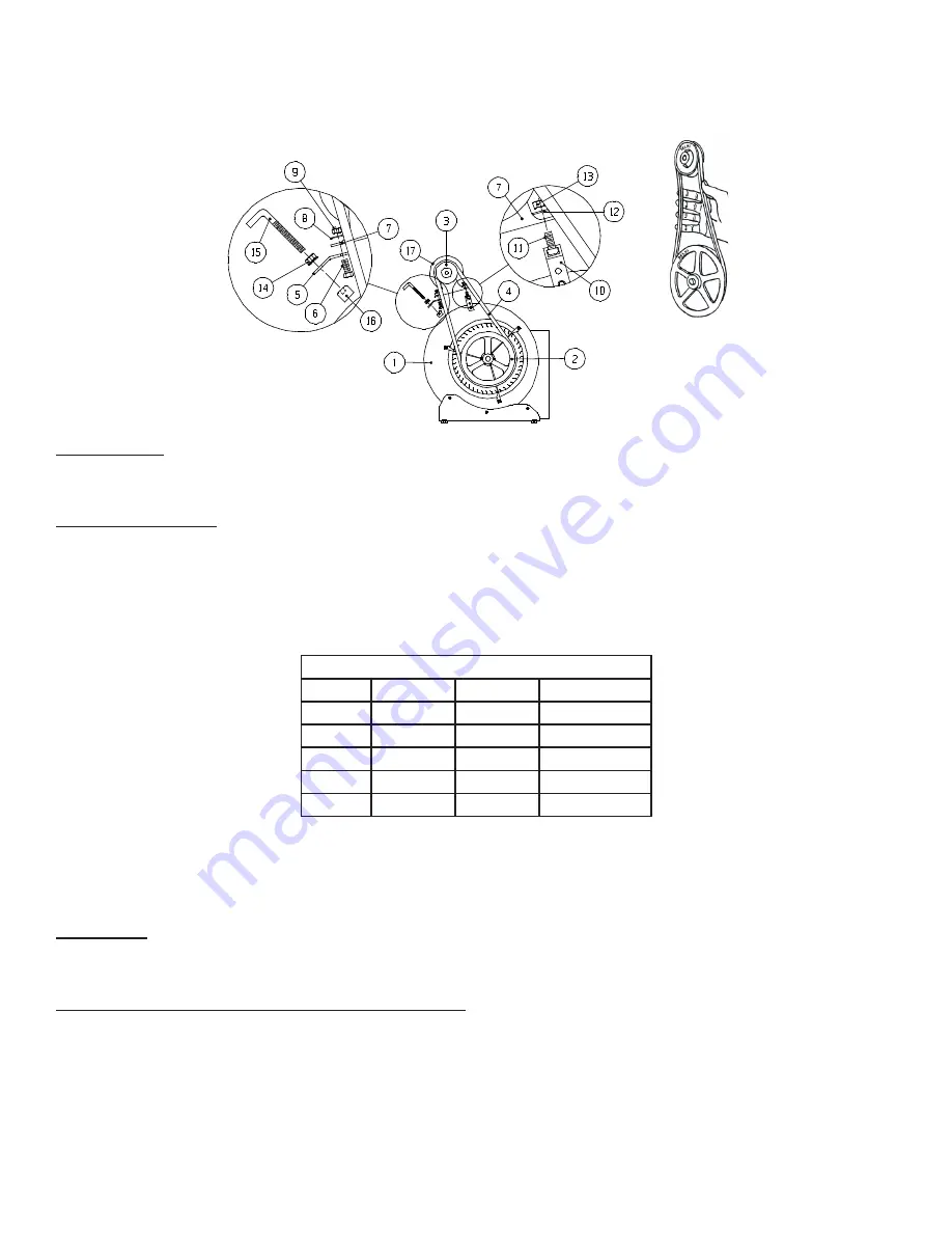
BELT TENSION
When adjusting the proper pulley setting make certain that the belt is able to flex at least one inch without
movement of the motor pulley.
DUCT INSTALLATION
To prevent excessive noise and temperature rise, limit the minimum return air duct size to at least 250 square inches
(in2). Because the unit may be used as a gravity furnace when the power is off, the following is recommended:
1. Locate the furnace as centrally as possible in the building so the best warm air distribution may be enjoyed.
2. Use an extended plenum (central duct) at least one size larger than called for in National Warm Air Standards.
3.
Use a minimum pipe size of six inches in diameter in runs and in no case smaller than five inch diameter.
4.
Slope extended plenum and runs as much as possible to facilitate gravity flow of warm air.
Minimum Duct Sizes
Model
Return Air Supply Air Static Pressure
CL86/96 250 sq. in. 180 sq. in.
.20” W.C.
CL115
250 sq. in. 220 sq. in.
.20” W.C.
CL140
250 sq. in. 220 sq. in.
.20” W.C.
CL155
280 sq. in. 240 sq. in.
.20” W.C.
CL170
300 sq. in. 260 sq. in.
.25” W.C.
The provided chart gives the MINIMUM free area duct size. The supply air extended plenum should be 8 – 10 feet
out from the furnace with the sizes shown in the chart, then gradually transitioned to the end of duct system. If
the plenum is lower than 24 inches high, increase the duct size proportionately. The Supply Air free area for CL-115
C&G is the same as CL-140 C&G because the wood burning portion of the furnace can produce 140,000 BTU.
HUMIDIFIER
Install humidifier in the return air plenum. This prevents possible damage due to excessive temperatures when
there is a power failure. Metal connecting ducting from the warm air plenum should be used.
OIL FIRED BLOCKED VENT SWITCH - MODEL WMO-1
Refer to the Newmac and Field Controls Instructions enclosed in the WMO-1 package.
Do not use the WMO-1 Blocked Vent Switch with the Newmac SVS Sealed Vent System
When installed on the chimney vent or on the appliance burner plate according to these instructions, the
manually reset WMO- 1 blocked vent switch is designed to shut off power to the oil burner if the hot flue gases
in the chimney vent connector pipe back up sufficiently to activate it. The WMO-1 switch is required on new
Newmac oil-fired and combination furnaces or boilers installed in Canada. It must be installed by a qualified
installer in accordance with the manufacturer’s installation instructions. Electrical wiring must be in accordance
with applicable codes and the Canadian Electrical Code. Before leaving the appliance check that the WMO-1
switch and its cover are tightly secured.
Figure 5
Figure 4
Summary of Contents for CL 115C
Page 7: ...7 Figure 7 FLUE PIPE CONNECTION MINIMUM INSTALLATION CLEARANCES...
Page 17: ...17 Figure 11 TYPICAL A C COIL INSTALLATION...
Page 18: ...18 Figure 12 WIRING DIAGRAM WITH AIR CONDITIONING...
Page 19: ...19 Figure 13 CL SERIES WIRING DIAGRAM...
Page 23: ...23 Figure 17 1E AERO PGB 220 370 GAS BURNER EXPLODED ASSLY...
Page 25: ...25 Figure 17 1G THERMO DISC MOUNTING ON BURNER PLATE...
Page 26: ...26 Figure 17 2A AERO BURNER EXPLODED ASSEMBLY...
Page 28: ...28 Figure 17 3A BECKETT BURNER EXPLODED ASSEMBLY...
Page 56: ...Figure 17 3A ASSEMBLAGE EXPLOD DU BR LEUR BECKETT...
Page 58: ...FIG 17 2A BR LEUR AERO ASSEMBLAGE CLAT...
Page 59: ...FIG 17 1G LE DISQUE DE THERMO MONTE SUR LA PLAQUE DE BR LEUR...
Page 64: ...FIG 13 C BLAGE DE LA S RIE CL...
Page 74: ...FIG 7 RACCORDEMENT DU TUYAU DE FUM E ET ESPACE LIBRE MINIMAL FIG 8 EMPLACEMENTS DES COMMANDES...


