3.3.2 Programmable outlet setting
The UPS is equipped with 2 programmable outlets for use to supply to less critical loads. These
outlets can be disabled to shed the less critical loads during back-up modes or overload
conditions to maintain quality power supply to the more critical loads connected to the UPS.
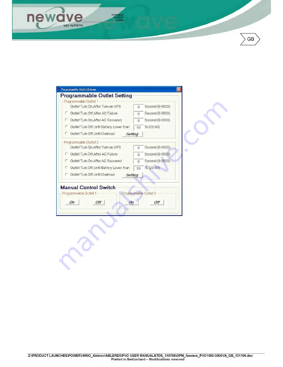
Click on the “Programmable outlet setting” bar to enter to the setting screen as shown below.
1. Outlet Turn On After Turn on UPS – select the time to automatically enable this outlet within the
specified time when the UPS is power on. If “0” sec is selected, the outlet will be enabled once
the UPS is power on.
2. Outlet Turn Off After AC Failure – select this option to automatically disable the outlet within the
specified time after utility outage to shed the less critical loads to provide longer battery back-up
time for the other more critical loads connected to the UPS.
3. Outlet Turn On After AC Recovered – select this option to automatically enable the outlet within
the specified time after the utility is restored.
4. Outlet Turn Off When Battery Lower than - select this option to automatically disable the outlet
at the specified remaining battery power capacity(%) during battery mode to shed the less
critical loads to prolong battery back-up time for the other more critical loads connected to the
UPS.
5. Outlet Turn Off When Overload – select this option to automatically disable the outlet during
overload condition (bypass mode) to possibly allow the more critical loads:
a) To be continually supplied via Bypass without shut down
b) To be transferred back to Inverter mode if the overload condition is removed by shedding
the less critical loads.
6. Click on “setting” to confirm the configurations. The UPS will sound 2 “beeps” to acknowledge
setting is successful.
7. Manual Control Switch – Click “On” or “Off” to manually enabled or disabled the programmable
outlets, overriding all previous settings.
Summary of Contents for 1000-3000VA
Page 13: ...4 3 Tower Configuration Setup Step 1 Step 2...
Page 14: ...Step 3 Step 4...
Page 15: ...4 4 Rack Mount Configuration Setup Step 3 Step 4 Step 5...
Page 16: ...Step 6 Step 7...
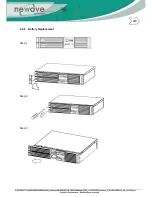
Page 19: ...4 5 6 Battery Replacement Step 1 Step 2 Step 3...
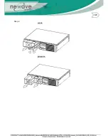
Page 20: ...Step 4...
Page 38: ...10 3 3 Installation Instructions Tower installation Stand alone unit Step 1 Step 2...
Page 39: ...Use with UPS Step 1 Step 2...
Page 40: ...10 3 4 Rack Mount installation Step 1 Step 2...
Page 41: ...Step 3 Step 4...
Page 42: ...Second Battery First Battery Bank UPS Connect DC Cable...
Page 44: ...Step 3 Step 4 10 3 7 Specifications...
Page 46: ...11 Technical Specifications...


