2-107
87519804 NA
Issued 11-06
Bur
CHAPTER 2 - 667TA ENGINE OVERHAUL
ENGINE REPAIR MANUAL
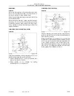
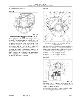
STEP 123
BS06K351
Figure 2-224
Install the EDC7UC31 electronic control unit (3)
including the heat exchanger to the engine block and
tighten the bolts (2), to the general bolt torque
specifications in the repair manual.
IMPORTANT:
Replace the vibration damper
elements (1).
CYLINDER HEAD
REMOVING THE VALVES
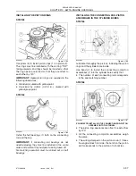
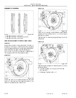
STEP 124
BS06K352
Figure 2-225
Intake (1) and exhaust (2) valves have heads with
the same diameter.
The central notch (
→
) of the exhaust valve (2) head
distinguishes it from the intake valve.
IMPORTANT:
Should cylinder head valves not be
replaced, number them before removing in order to
install them in the same position.
A = Intake side
S = Exhaust side
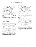
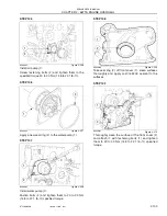
STEP 125
BS06K353
Figure 2-226
Va l ve s c a n b e r e m o ve d w i t h a va l ve s p r i n g
compressor tool (1) by pressing slightly on collar (3)
s o t h a t l o c k c o n e s ( 2 ) c a n b e r e m o v e d b y
compressing springs (4).
Then remove collar (3) and springs (4).
Repeat the operation on all valves.
Turn the head upside down and remove the valves
(5).
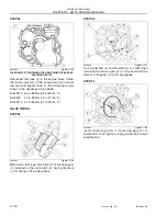
STEP 126
BS06K354
Figure 2-227
Remove the sealing rings (1 and 2) from the valve
guides.
IMPORTANT:
Sealing rings (1) for intake valves are
yellow.
Sealing rings (2) for exhaust valves are green.
1
2
3
1
2
S
A
1
2
3
4
5
1
2
Summary of Contents for 667TA/EBF
Page 4: ...SECTION 1 ENGINE REPAIR MANUAL II Issued 11 06 Bur 87519804 NA NOTES ...
Page 8: ...1 2 Issued 11 06 Bur 87519804 NA CHAPTER 1 DIAGNOSTICS ENGINE REPAIR MANUAL NOTES ...
Page 16: ...1 10 Issued 11 06 Bur 87519804 NA CHAPTER 1 DIAGNOSTICS ENGINE REPAIR MANUAL NOTES ...
Page 22: ...2 4 Issued 11 06 Bur 87519804 NA CHAPTER 2 667TA ENGINE OVERHAUL ENGINE REPAIR MANUAL NOTES ...
Page 144: ...3 2 Issued 11 06 Bur 87519804 NA CHAPTER 3 CHARGING AND START UP ENGINE REPAIR MANUAL NOTES ...
Page 150: ...3 8 Issued 11 06 Bur 87519804 NA CHAPTER 3 CHARGING AND START UP ENGINE REPAIR MANUAL NOTES ...


